Support structure for solar plants and method for mounting

a technology for solar plants and support structures, applied in the direction of solar-ray concentration, heat collector mounting/support, bottle holders, etc., can solve the problems of relative high production costs, maintenance problems, and difficulty in adjusting clamping means

Inactive Publication Date: 2014-10-21
VETRARIA BIANCADESE DI LUCATELLO & C
View PDF11 Cites 1 Cited by
  • Summary
  • Abstract
  • Description
  • Claims
  • Application Information

AI Technical Summary

Benefits of technology

[0018]In this way, the action of the elastic means in traction on the adjustment means determines a greater accuracy and safety in clamping the reflection plate, allowing to recover, in an optimized manner, possible plays in assembly, to distribute the traction on the edges of the plates and to compensate possible variations in size of the reflection plate, caused by heat variations, variations in size and variations caused by wear.
[0019]The present invention therefore guarantees, simply and economically, that the intensity of the clamping action is accurately adjusted, and that the adjustment position reached is maintained.
[0025]According to another variant of the present invention the seat where the elastic means operate cooperates with means that condition the widening of the elastic means, and allow them to stiffen.

Problems solved by technology

One disadvantage of known support structures is that the current clamping means provide complex combinations of screws, springs, levers or other which, apart from making the operations to install / remove the reflection plates long and expensive, also have relatively high production costs, and problems with maintenance over time.
Moreover, known clamping means are difficult to adjust in order to vary the degree of deformation of the plate and, in any case, they do not allow an accurate adjustment due to the plays of assembly and possible deformations in size also due to variations in temperature.

Method used


Image

  • Support structure for solar plants and method for mounting
  • Support structure for solar plants and method for mounting
  • Support structure for solar plants and method for mounting

Examples


Embodiment Construction

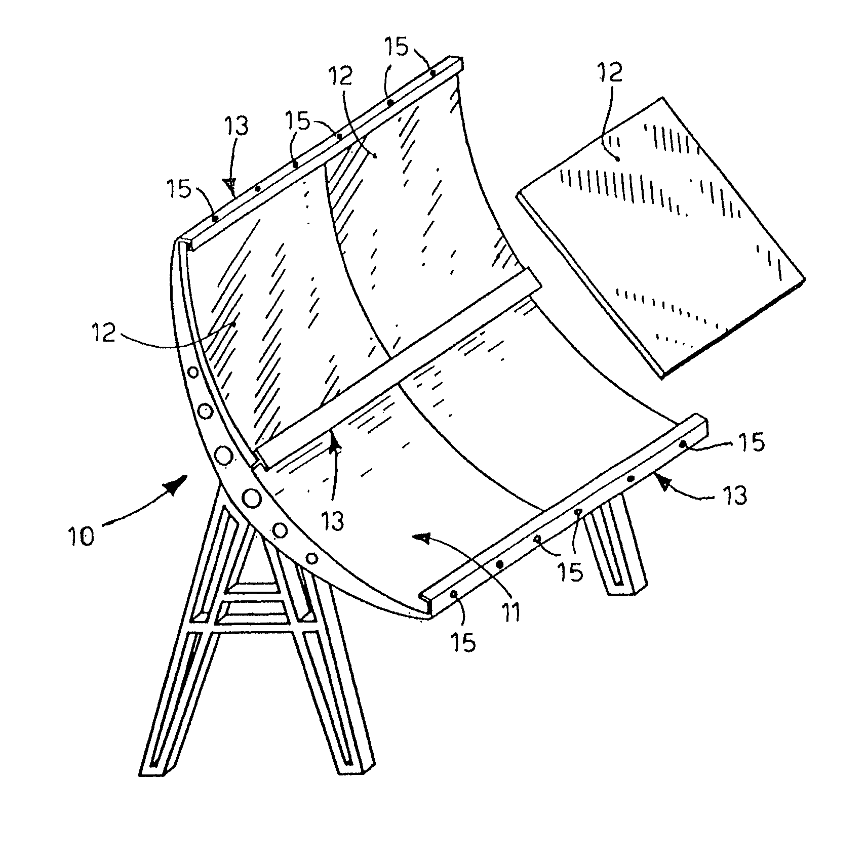
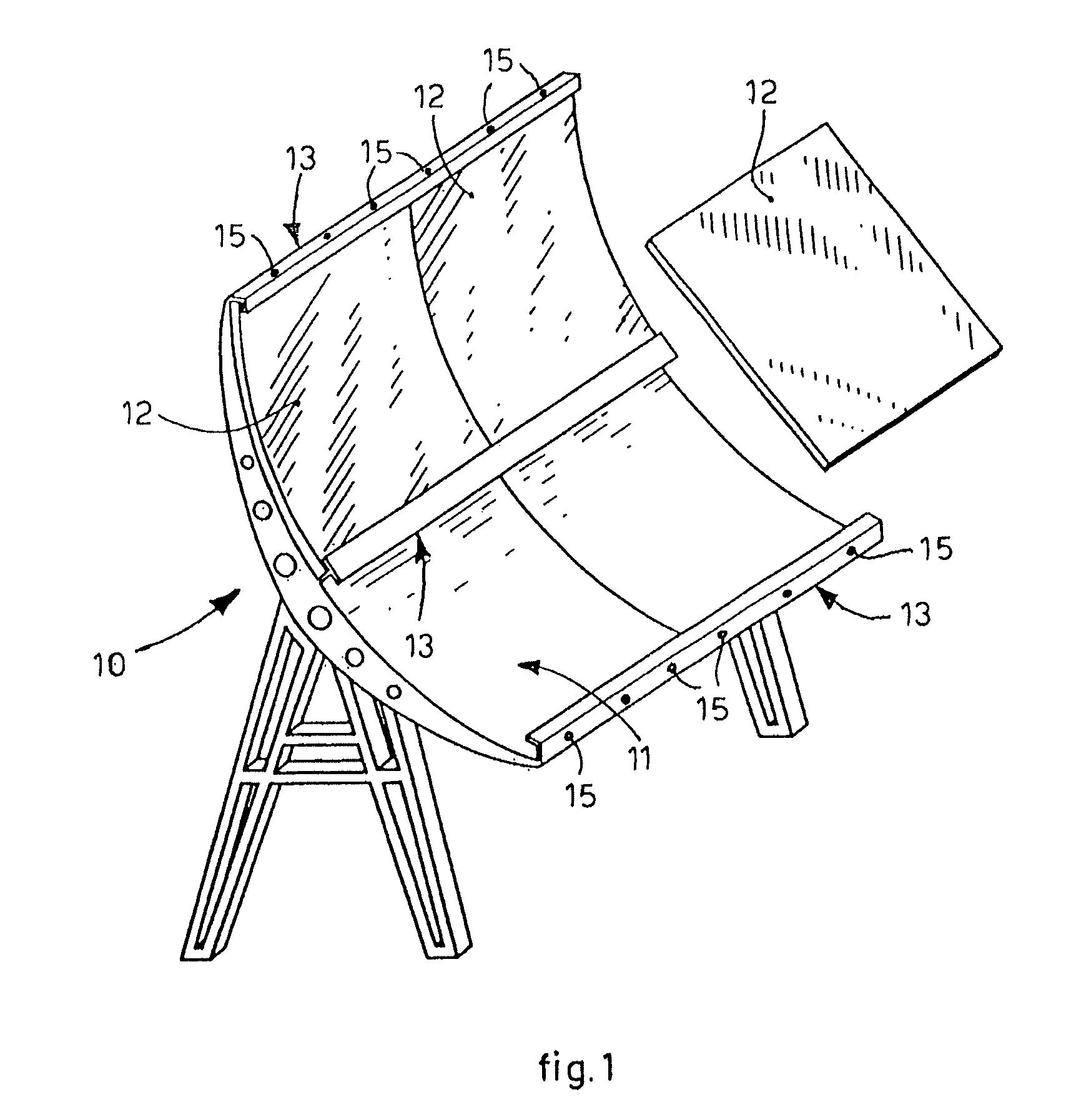
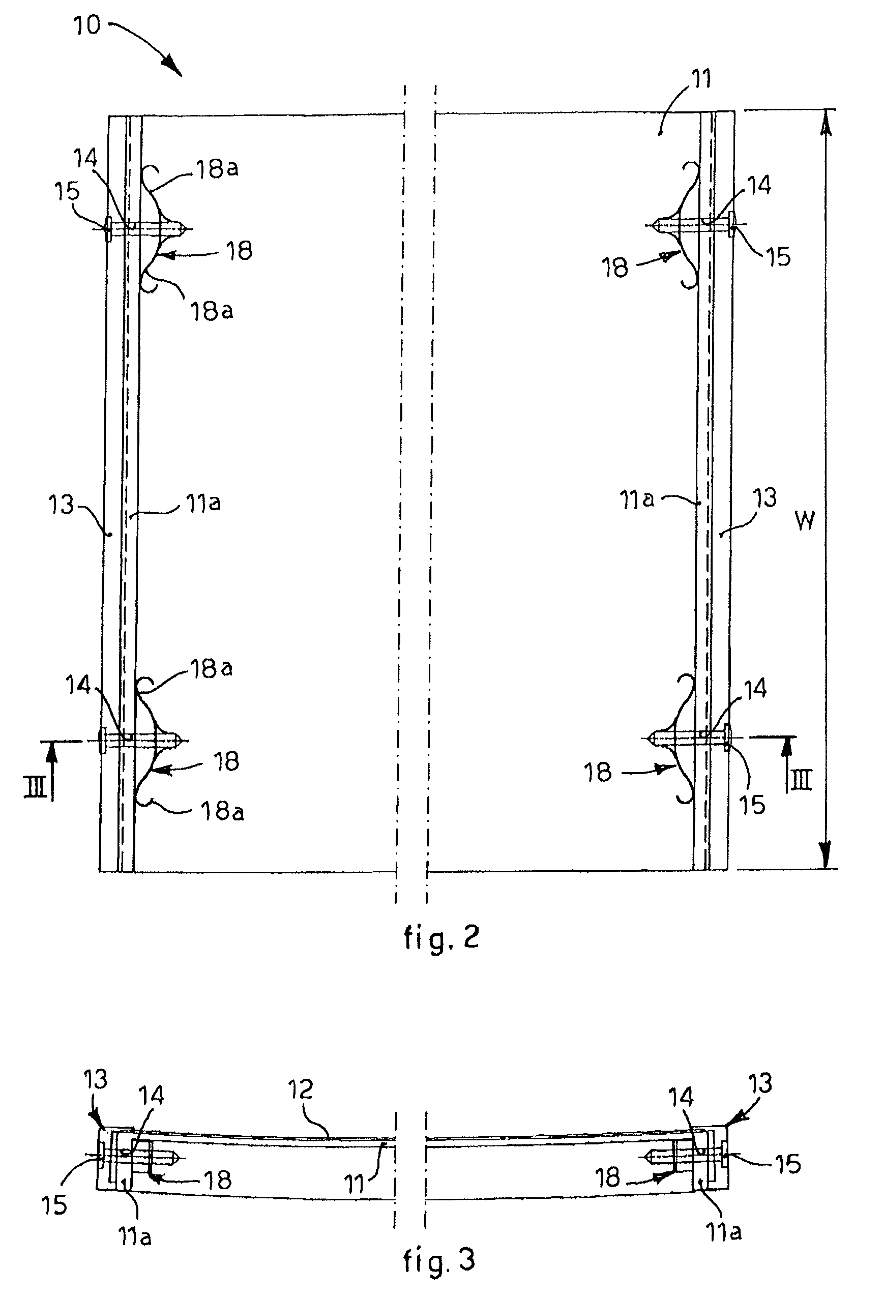
[0033]With reference to the attached drawings, a variably configured support structure 10 is able to be used in solar plants of the concentration type, and comprises a supporting wall 11, able to support one or more reflection plates 12, thin and flexible, suitable to reflect the sun's rays and concentrate them in correspondence with collectors to exploit the solar energy, present on the support structure 10 and not shown in the drawings.

[0034]The supporting wall 11 is shaped so as to define a substantially parabolic and desired profile and is associated along two of its opposite edges with clamping elements 13, mobile with respect to the supporting wall 11 and functioning as retainers. In this case the clamping elements 13 are conformed as structural shapes, substantially C-shaped.

[0035]The clamping elements 13 are suitable to clamp the plates 12 in relation to the support structure 10 until they are conformed according to the parabolic profile of the supporting wall 11.

[0036]Advan...


PUM

PropertyMeasurementUnit
flexibleaaaaaaaaaa
elasticaaaaaaaaaa
compression forcesaaaaaaaaaa

Abstract

Support structure, comprising a supporting wall, advantageously with a substantially parabolic profile or suchlike, for solar plants of the concentration type, and able to support at least a thin and flexible reflection plate, able to reflect the sun's rays in order to concentrate them in correspondence with collectors to exploit the solar energy. The support structure comprises clamping elements movable with respect to the supporting wall, and able to clamp the reflection plate in cooperation with the supporting wall. The support structure comprises adjustment means constrained to the clamping elements and able to cooperate with relative elastic means constrained to the supporting wall. The elastic means are disposed and conformed with respect to the supporting wall so as to exert an action of traction on the adjustment means and on the clamping elements, so as to exert the desired action of deformation on the reflection plate.

Description

FIELD OF THE INVENTION[0001]The present invention concerns a support structure for solar plants. In particular the support structure according to the present invention is used in concentration type solar plants to support a plurality of reflection plates suitable to concentrate the sun's rays in suitable collectors, in order to exploit the solar energy.BACKGROUND OF THE INVENTION[0002]In solar plants of the concentration type, it is known to use curved support structures to support a plurality of reflection plates made of glass or other suitable material, thin and flexible, able to reflect the sun's rays to concentrate them in suitable collectors, advantageously present on the structure, so as to exploit the solar energy.[0003]The reflection plates are associated, either flat or curved in advance, with the support structure by means of clamping elements provided in at least one of the two opposite edges of the support structure and able to clamp the reflection plates on the structur...

Claims


Application Information

Patent Timeline
Patent Type & Authority Patents(United States)
IPC IPC(8): F24J2/52F24J2/12B23P15/26F24J2/14F24S23/71F24S23/74
CPCF24J2/145F24J2/5258F24J2002/5284Y02E10/45Y02E10/47Y10T29/49947Y10T29/49355F24S23/745F24S25/636F24S2025/016Y02E10/40
Inventor COGLIATI, DOMENICO, PAOLO, MARIA
Owner VETRARIA BIANCADESE DI LUCATELLO & C
Why Eureka
Try Eureka