
Noise measurement apparatus for image signal and method thereof

Inactive Publication Date: 2005-12-08
SAMSUNG ELECTRONICS CO LTD
View PDF9 Cites 25 Cited by
  • Summary
  • Abstract
  • Description
  • Claims
  • Application Information

AI Technical Summary

Benefits of technology

[0018] In order to solve the above and / or other problems, the present general inventive concept provides a noise measurement apparatus which is capable of reducing an error when measuring a noise in an image signal, and a method thereof.
[0019] The present general inventive concept also provides is to provide a noise measurement apparatus which is capable of reducing an error when measuring a noise in an image having no plane area.

Problems solved by technology

When an image signal-processing device, such as televisions or video tape recorders, is supplied with image signals, it is often the case that a noise is entrained in the image signals.
The noise in the image signals typically causes a reduction in the quality of images in video signals.
Therefore, the noise measurement cannot be implemented adaptively to characteristics of the image signals, and thus an error occurs.
For example, when the entire image has no plane area, the error may occur in the noise measurement.

Method used


Image

  • Noise measurement apparatus for image signal and method thereof
  • Noise measurement apparatus for image signal and method thereof
  • Noise measurement apparatus for image signal and method thereof

Examples


Embodiment Construction

[0031] Reference will now be made in detail to the embodiments of the present general inventive concept, examples of which are illustrated in the accompanying drawings, wherein like reference numerals refer to the like elements throughout. The embodiments are described below in order to explain the present general inventive concept while referring to the figures.

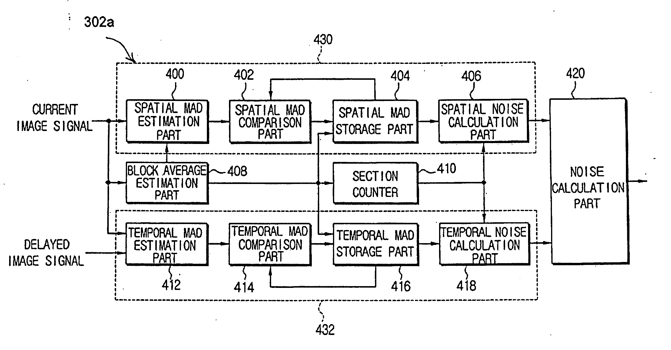
[0032] The present general inventive concept describes a method of reducing an error of a noise measured by using both a spatial area and a temporal area of an image signal.

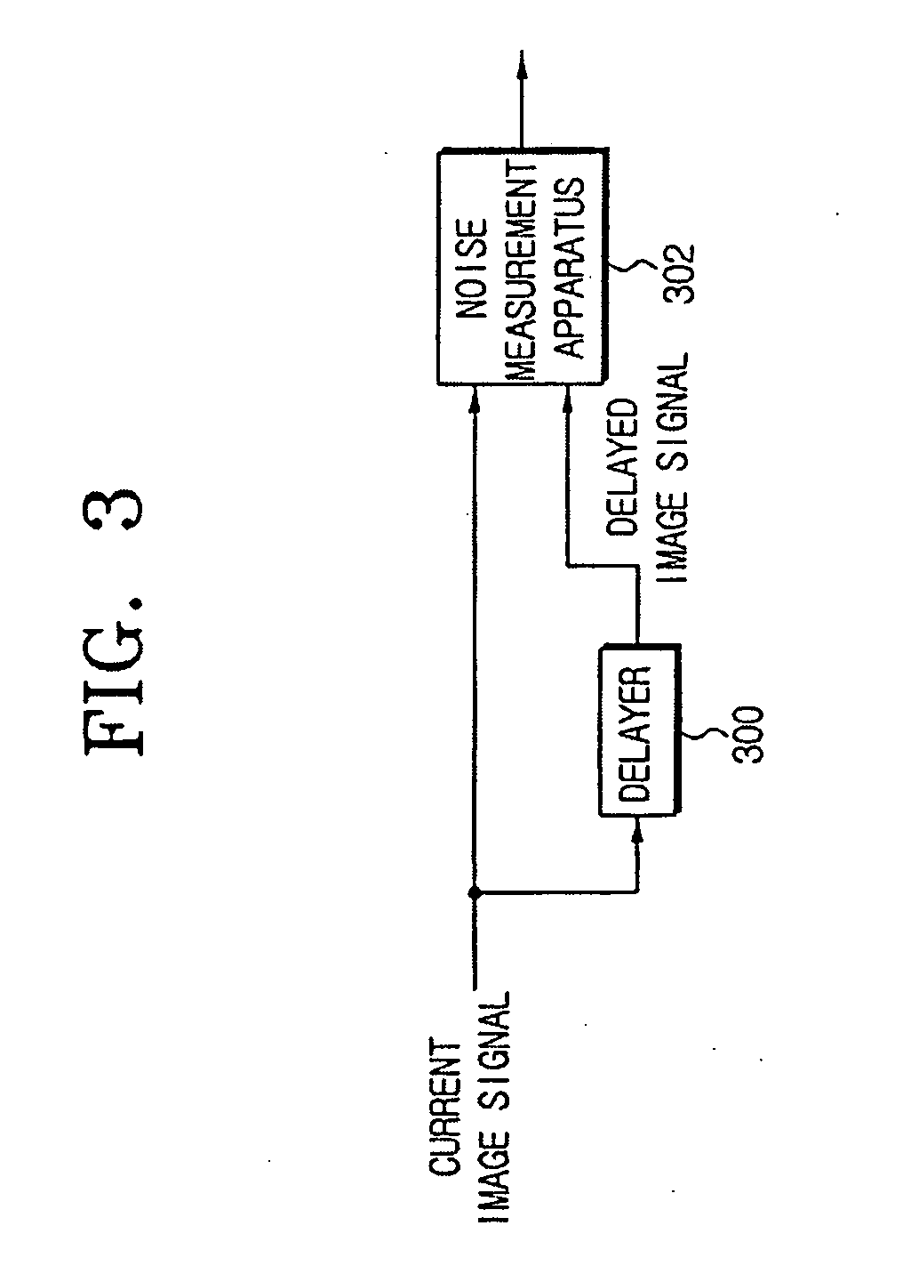
[0033]FIG. 3 illustrates an image signal inputted to a noise measurement apparatus 302 according to the present general inventive concept. The noise measurement apparatus 302 is inputted with a current image signal and a one-picture-delayed image signal which is obtained by a delayer 300. Although FIG. 3 depicts the image signal is delayed by the delayer 300, this should not be considered as limiting. That is, the noise measurement apparatus 302 may be ...


PUM


Abstract

A noise measurement apparatus and a method thereof capable of reducing an error in measuring a noise of incoming image signals. A picture of an incoming image signal is broken into at least two blocks and an average brightness value with respect to each block is calculated in a sequence. At least two first data, each being a sum of differences between the calculated average brightness value and brightness values of respective constituent pixels of the block, where the average brightness value is calculated, and a spatial noise is calculated based on the at least two first data. At least two second data that indicate a difference a brightness value of each block of the picture and a brightness value of each block of a delayed picture is calculated, and a temporal noise is calculated based on the at least two second data. A noise on the image signal is calculated based on the spatial noise and the temporal noise.

Description

CROSS-REFERENCE TO RELATED APPLICATIONS [0001] This application claims the benefit under 35 U.S.C §119 (a) of Korean Patent Application No. 2004-41929, filed on Jun. 8, 2004, in the Korean Intellectual Property Office, the disclosure of which is incorporated herein by reference in its entirety. BACKGROUND OF THE INVENTION [0002] 1. Field of the Invention [0003] The present general inventive concept relates to an apparatus and method to provide noise measurement in image signals. More particularly, the present general inventive concept relates to an apparatus and method of measuring noise in image signals according to spatial and temporal frequency components, thereby enhancing efficiency of removing the noise. [0004] 2. Description of the Related Art [0005] When an image signal-processing device, such as televisions or video tape recorders, is supplied with image signals, it is often the case that a noise is entrained in the image signals. The noise in the image signals typically ca...

Claims


Application Information

Patent Timeline
IPC IPC(8): G06K9/00H04N17/02H04N5/217H04N5/208H04N5/21H04N17/00G06T5/00
CPCH04N17/00G06T5/002G06T5/20G06T5/50G06T2207/20021G06T5/70H04N5/208H04N5/21
Inventor YU, PIL-HO
Owner SAMSUNG ELECTRONICS CO LTD
Learn More