
Image registration system and method

a technology of image registration and registration method, applied in the field of image processing, can solve the problems of individual image misalignment, computational cost, time-consuming,

Inactive Publication Date: 2005-12-08
PHOTON RES ASSOCS
View PDF16 Cites 56 Cited by
  • Summary
  • Abstract
  • Description
  • Claims
  • Application Information

AI Technical Summary

Problems solved by technology

As sequences of images are collected, for example by a motion picture camera, individual images may be misaligned due to the movement of the camera.
To simultaneously estimate the four parameters, a non-linear inverse problem is solved that is computationally expensive (i.e., time consuming).
In some applications such as collecting image sequences (e.g., video) with a camera mounted on an unmanned aerial vehicle (UAV), the excessive processing time for simultaneously estimating the four parameters negates the real time utility of such an approach because of the accumulating time lag between the raw video and the processed video.

Method used


Image

  • Image registration system and method
  • Image registration system and method
  • Image registration system and method

Examples


Embodiment Construction

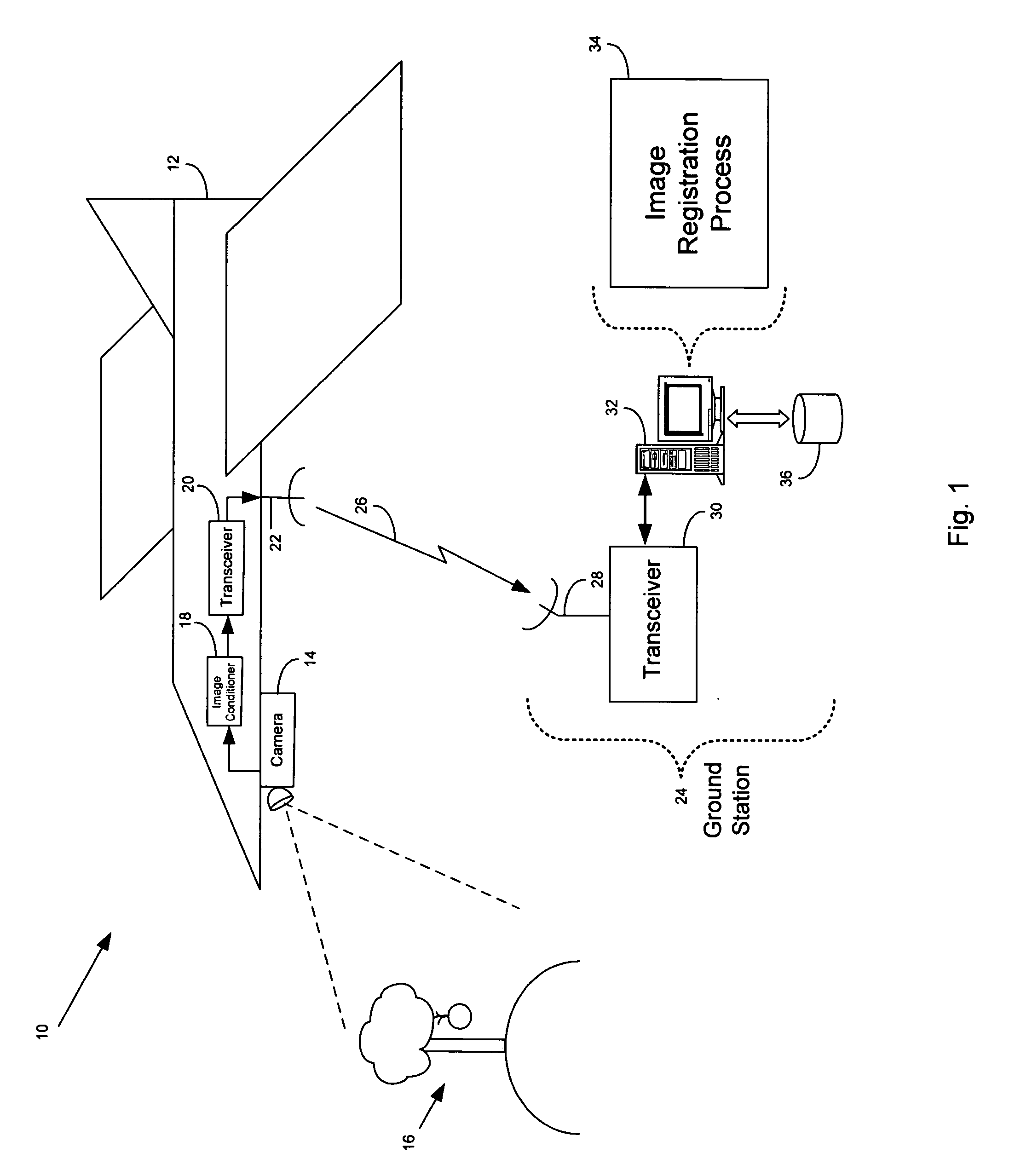
[0028] Referring to FIG. 1, a system 10 for collecting and processing aerial images includes an unmanned aerial vehicle (UAV) 12 in flight that has a camera 14 payload for collecting image sequences for applications such as battlefield monitoring, intelligence gathering, or other similar mission. Typically the camera 14 operates in the visual band to collect photographic images, however, in some arrangements the camera operates in the infrared band or other portion of the electromagnetic spectrum to collect images. The camera 14 collects a sequence of images as the UAV 12 flies over a photographic subject 16 (e.g., buildings, landscape, etc.) such as an apple tree. As the image sequence is collected by the camera 14, the images are passed to an image conditioner 18 which processes the images for storage and transmission. For example, the image conditioner 18 may add a unique time stamp or data representing the location of the UAV 12 (e.g., a GPS location) to each image collected. In...


PUM


Abstract

A method of characterizing alignment between two images includes receiving a first data set representative of a reference image, receiving a second data set representative of a target image, processing the first and second data sets that includes calculating an autocorrelation of the first data set to obtain a third data set that is substantially absent information representative of a relative shift between the reference image and the target image, and processing the third data set that includes calculating a Radon transform of the autocorrelation of the first data set to obtain a fourth data set that includes information representative of a relative rotational difference between the reference image and the target image.

Description

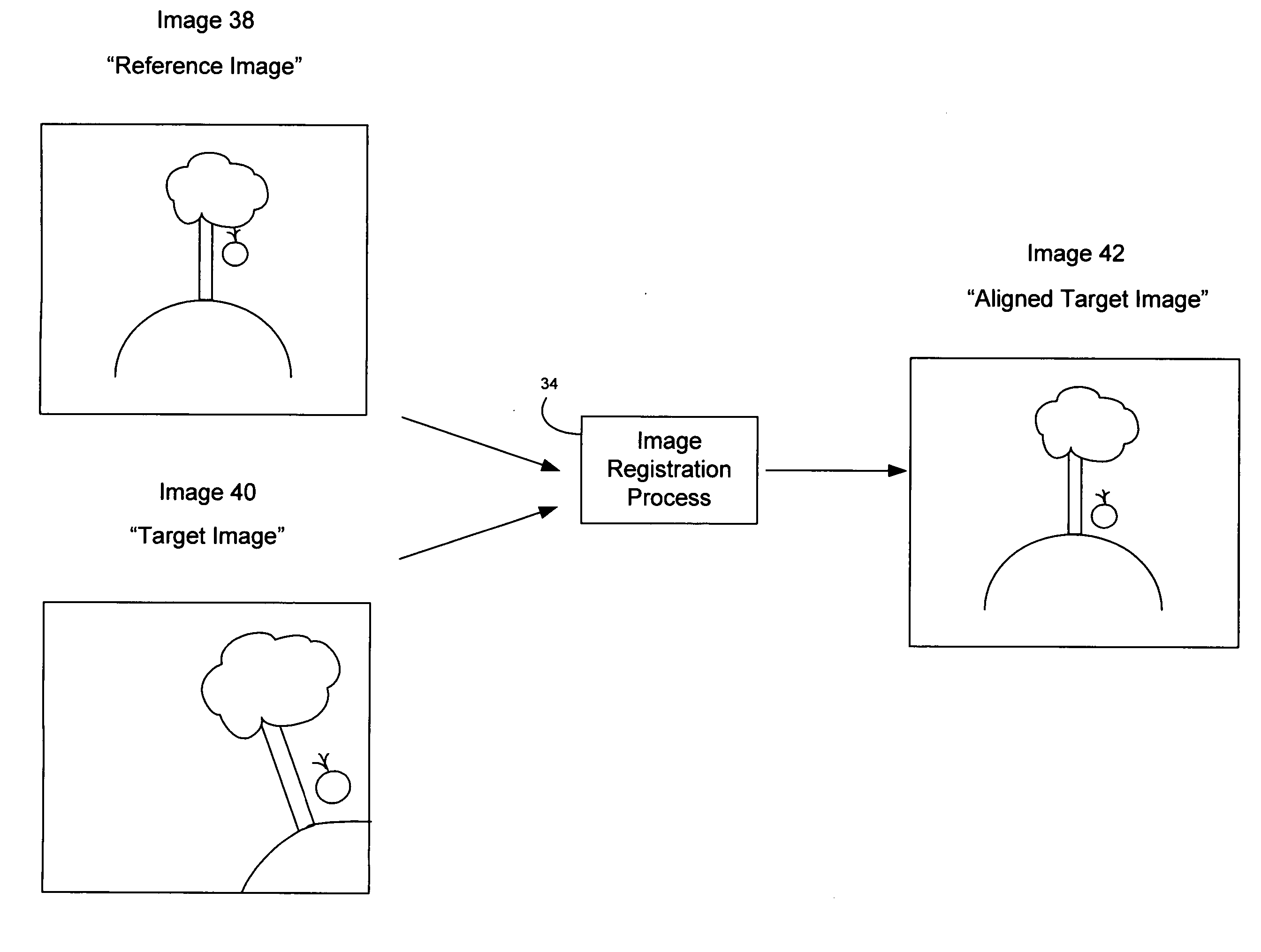
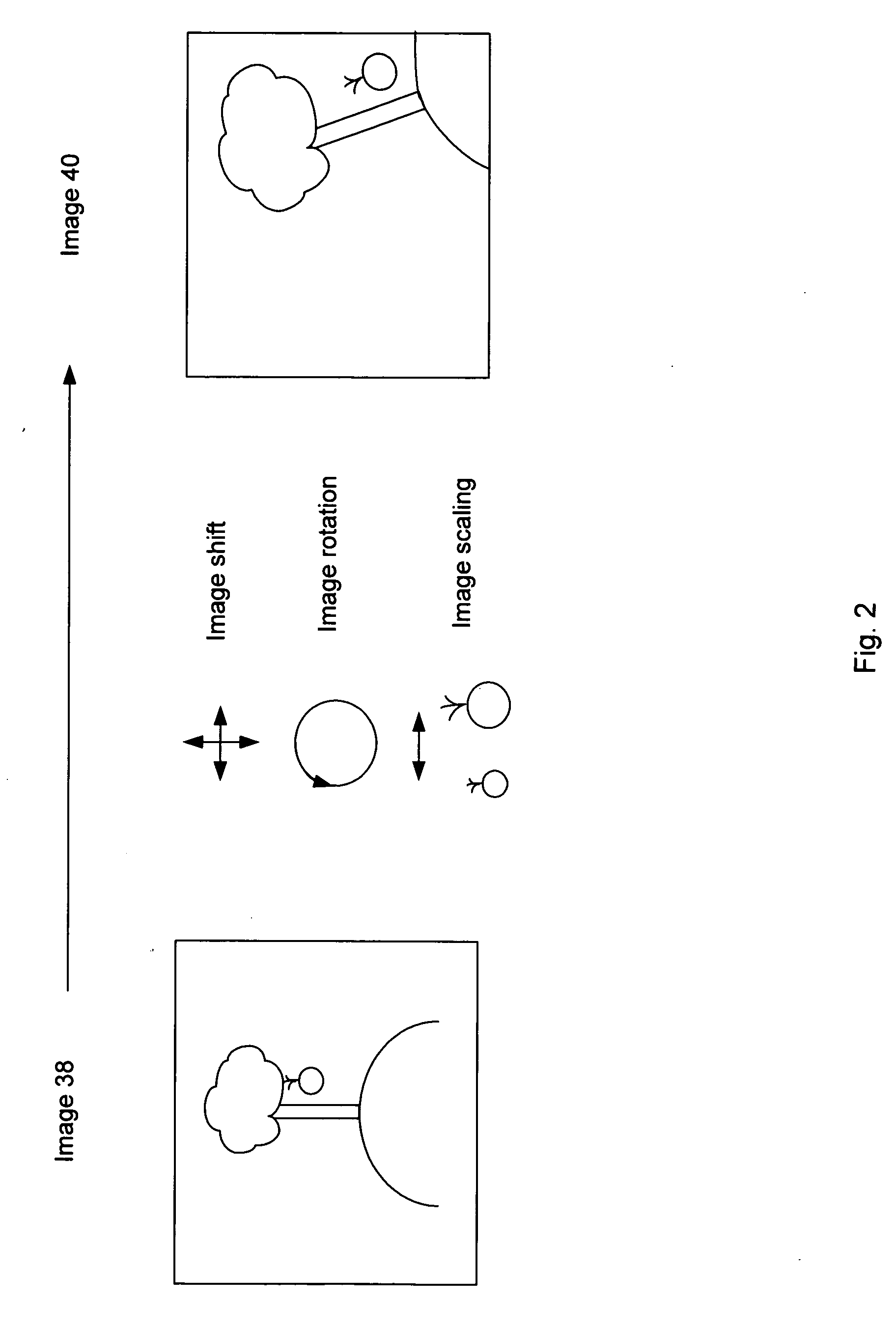
FIELD OF THE INVENTION [0001] This invention relates to image processing and, more particularly, to image registration. BACKGROUND [0002] As sequences of images are collected, for example by a motion picture camera, individual images may be misaligned due to the movement of the camera. In particular, camera movements occurring between the collecting of two sequential images may cause the second image to appear shifted in position and rotated relative to the previously collected image. Furthermore other image misalignments may be introduced such as scale changes, shear, and parallax due to camera optics. Considering misalignments due to relative shifting, rotating, and scaling differences, four parameters are needed to characterize these misalignments. To simultaneously estimate the four parameters, a non-linear inverse problem is solved that is computationally expensive (i.e., time consuming). In some applications such as collecting image sequences (e.g., video) with a camera mounte...

Claims


Application Information

Patent Timeline
Patent Type & Authority Applications(United States)
IPC IPC(8): G06K9/64G06K9/32G06K9/46G06K9/52
CPCG06K9/4647G06K9/522G06K9/6212G06V10/507G06V10/431G06V10/758
Inventor PINA, ROBERT K.
Owner PHOTON RES ASSOCS
Learn More