
Passive measurement of terrain parameters

a technology of terrain parameters and measurement methods, applied in the direction of vehicle position/course/altitude control, process and machine control, instruments, etc., can solve the problems of affecting accuracy, stereo measurement is an unsuitable technology for determining distance, and is generally not advisable to rely on an external system. , to achieve the effect of accurate and reliabl

Inactive Publication Date: 2005-12-08
SAAB AB
View PDF6 Cites 18 Cited by
  • Summary
  • Abstract
  • Description
  • Claims
  • Application Information

AI Technical Summary

Benefits of technology

The present invention provides a method for accurately determining terrain parameters relative to a vehicle by using a minimum of input data. This method involves receiving vehicle movement data, such as translation and rotation vectors, and resolving a terrain vector from these data. The terrain vector describes the movement of the vehicle's terrain points in relation to the vehicle's position. The method can be implemented using a computer program or an on-board arrangement for determining the terrain parameters. The invention offers a reliable and accurate solution for determining these parameters, even when the vehicle's position is not known.

Problems solved by technology

In military applications, however, it is generally not advisable to rely on an external system such as a GNSS, since this type of system may be struck out or its signals may be spoofed and / or distorted.
Therefore, stereo measurement is an unsuitable technology for determining the distance between an aircraft and the ground.
One important factor, which may severely influence the accuracy is that the angular sensor may be oriented differently when recording the second image than when recording the first image.
Of course, this problem is particularly accentuated in aircraft applications.
Although today's inertial sensors (e.g. including gyros, microactuators, and / or microsensors) may provide very accurate translation data, it is still problematic to register the relevant rotation with sufficiently high accuracy.
Consequently, the calculated range is not a reliable figure either.

Method used


Image

  • Passive measurement of terrain parameters
  • Passive measurement of terrain parameters
  • Passive measurement of terrain parameters

Examples


Embodiment Construction

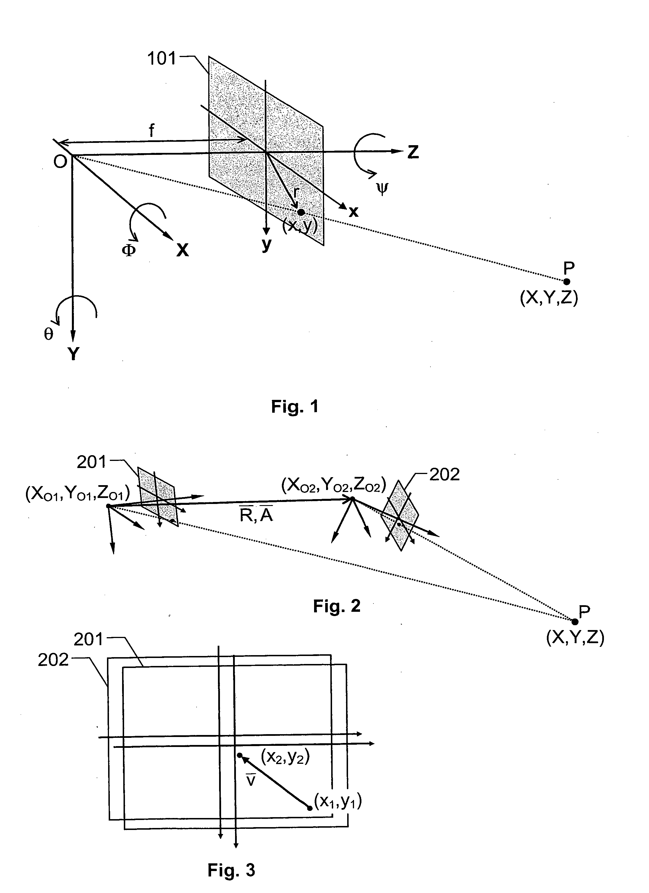
[0034] A camera may be described geometrically by means of a so-called central projection model. FIG. 1 illustrates such a model of a camera having a focal length f. This means that all light rays that enter the camera cross one another at a focal point O, which lies at a distance f behind an image plane 101 along a central optical axis Z. The image plane 101, in turn, is spanned by coordinate axes X and Y, which are both perpendicular to the optical axis Z. Thus, the focal point O represents a projection center, and the camera direction is given by the optical axis Z.

[0035] Specifically, when registering an image that includes a terrain point P, light from the point P is projected onto the image plane 101, so that the point P is represented at image coordinates (x,y) in the image plane 101. Hence, the camera may be regarded as an angular sensor, since the image coordinates (x,y) and the focal length f can be expressed in polar coordinates (r,θ,Φ), where r denotes an unknown distan...


PUM


Abstract

The present invention relates to determination of a terrain parameter relative to a vehicle (100) by registering a first image from the vehicle (100) when it is located at a first point in space (O1). The first image includes a primary representation of a first terrain point (P1) and a primary representation of a second terrain point (P2). Then, a second image is registered from the vehicle (100) when it is located at a second point in space (O2). This second image includes secondary representations of the first and secondary terrain points (P1) and (P2) respectively. Moreover, vehicle movement data is received, which describes at least one of a translation ({overscore (R)}) between the first and second points in space (O1; O2), and a rotation ({overscore (A)}) between the first and second points in space (O1; O2). A first image velocity vector is determined, which describes a movement of the primary representation of the first terrain point (P1) in the first image to the secondary representation thereof in the second image. Correspondingly, a second image velocity vector is determined, which describes a movement of the primary representation of the second terrain point (P2) in the first image to the secondary representation thereof in the second image. A terrain vector ({overscore (Ξ)}) is then resolved, based on the first and second images, a camera model describing a geometric relationship between a particular terrain point and its projected representation onto an image plane, and a respective relationship expressing each of the first and second image velocity vectors as a function of the translation ({overscore (R)}) and the rotation ({overscore (A)}). The terrain vector ({overscore (Ξ)}) extends between one of the first and second points in space (O1; O2) and a particular terrain point (T) in proximity of the vehicle (100). Thus, based on the terrain vector ({overscore (Ξ)}), for instance an altitude (ZO1) of the vehicle (100) may be determined.

Description

THE BACKGROUND OF THE INVENTION AND PRIOR ART [0001] The present invention relates generally to passive determination of terrain parameters in relation to a vehicle. More particularly the invention relates to a method of determining a terrain parameter according to the preamble of claim 1 and an on-board arrangement according to the preamble of claim 10. The invention also relates to a computer program according to claim 7, a computer readable medium according to claim 8 and an air vehicle according to claim 16. [0002] Today, there exist many alternative means of navigation aids for vehicles, such as aircrafts. For instance, in the last decades, global navigation satellite systems (GNSS:s) have been developed which render it possible to determine a vehicle's position on the basis of accurate radio signals received from a plurality of satellites (at least four). The most wide spread GNSS standards are represented by the U.S. GPS (Global Positioning System), the Russian correspondence...

Claims


Application Information

Patent Timeline
Patent Type & Authority Applications(United States)
IPC IPC(8): B64C1/00G01C5/00G01C11/06G06F7/00
CPCG01C5/005G01C11/06
Inventor QWARFORT, FREDRIKASKMALM, LEIF
Owner SAAB AB
Learn More