Gas turbine engine inlet with noise reduction features

a technology of gas turbine engines and inlet areas, applied in the direction of machines/engines, mechanical equipment, transportation and packaging, etc., can solve the problems of primarily generated aircraft noise, particularly disturbing noise, and attracted attention to noise generated by flying aircraft, so as to reduce the inlet area, and increase the acoustic attenuation

Inactive Publication Date: 2005-12-15
UNITED TECH CORP
View PDF11 Cites 74 Cited by
  • Summary
  • Abstract
  • Description
  • Claims
  • Application Information

AI Technical Summary

Benefits of technology

[0007] According to the present invention, a gas turbine engine comprises a nacelle enclosing a fan section, a compressor, a combustor and a turbine, with the nacelle including an inner nacelle surface defining an inlet duct and means for reducing an inlet duct area of the inlet duct to increase acoustic attenuation during certain conditions of an aircraft. The means for reducing the inlet area is disposed on an inner nacelle surface or on a spinner, disposed forward of the fan section, or on both, the inner nacelle surface and the spinner surface.
[0008] In one embodiment of the present invention, the means for reducing the inlet area includes a nacelle contoured surface protruding radially inward from the inner nacelle surface to reduce the inlet duct area. In another embodiment of the present invention, the means for reducing the inlet area includes a spinner contoured surface protruding into the inlet duct to reduce the inlet duct area. In yet another embodiment, the means for reducing the inlet area comprises means for selectively reducing the inlet area. In a further embodiments, the means for selectively reducing the inlet area comprises an inflatable bladder, a SMA actuator, a fluidic actuator, or a combination thereof. The inflatable bladder, the SMA actuator, and the fluidic actuator are disposed on an inner nacelle surface or on a spinner, or on both, the inner nacelle surface and the spinner surface. The means for selectively reducing the inlet area may be also used in combination with the nacelle and / or spinner contoured surfaces.
[0009] The foregoing and other advantages of the present invention become more apparent in light of the following detailed description of the exemplary embodiments thereof, as illustrated in the accompanying drawings.

Problems solved by technology

In recent years, noise generated by flying aircraft has attracted attention and is now subject of various governmental regulations.
The noise is especially disturbing during certain flight conditions such as takeoffs and landings of the aircraft.
The aircraft noise is primarily generated by gas turbine engines propelling the aircraft.
One major source of the noise generated by the gas turbine engine is the fan section.
Frequently, optimization of one factor results in undesirable consequences for another.
Although noise generated by the gas turbine engine is now subject to fairly stringent governmental regulations, to date, the noise considerations were not part of the design optimization for conventional engines.

Method used


Image

  • Gas turbine engine inlet with noise reduction features
  • Gas turbine engine inlet with noise reduction features
  • Gas turbine engine inlet with noise reduction features

Examples


Embodiment Construction

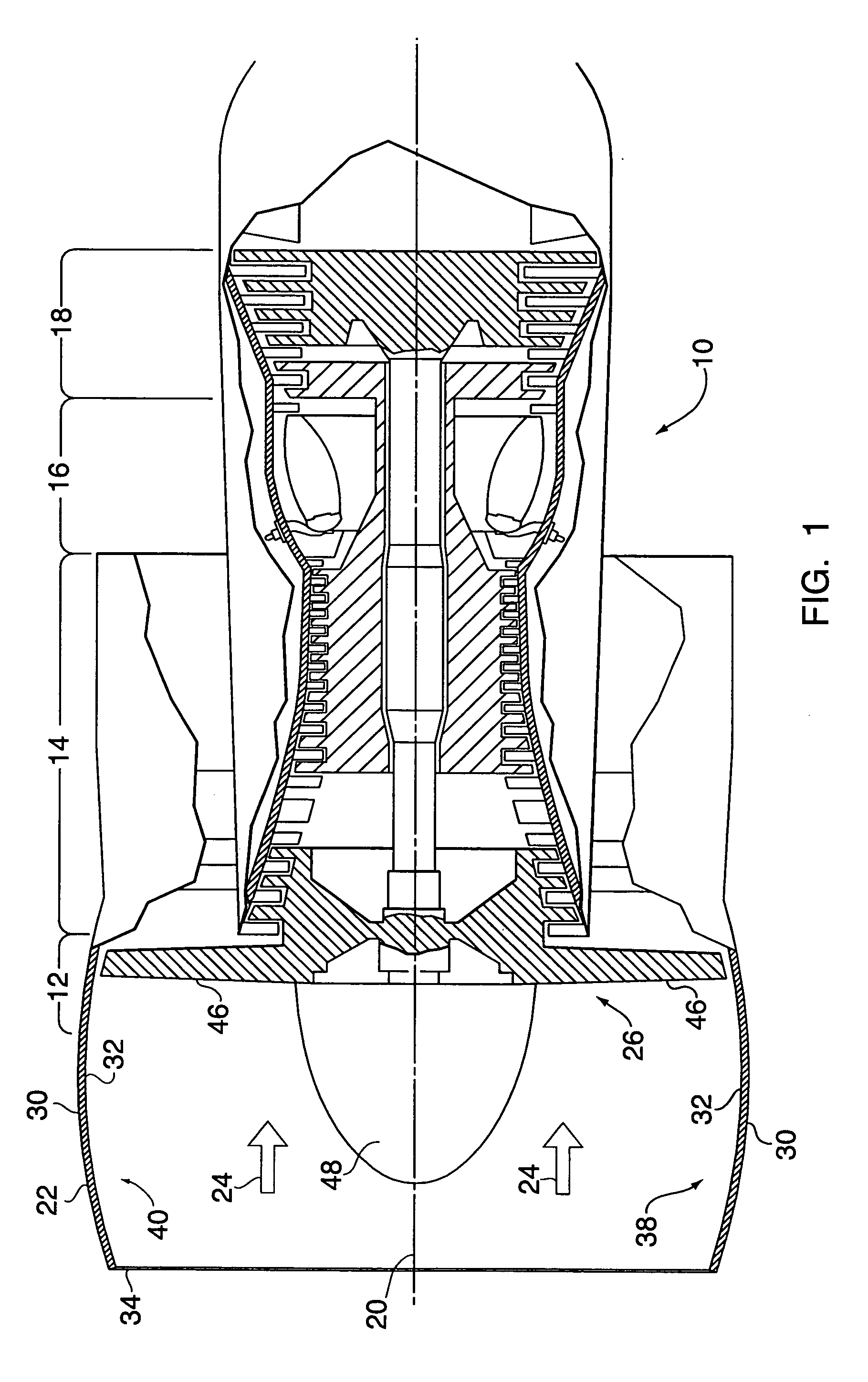
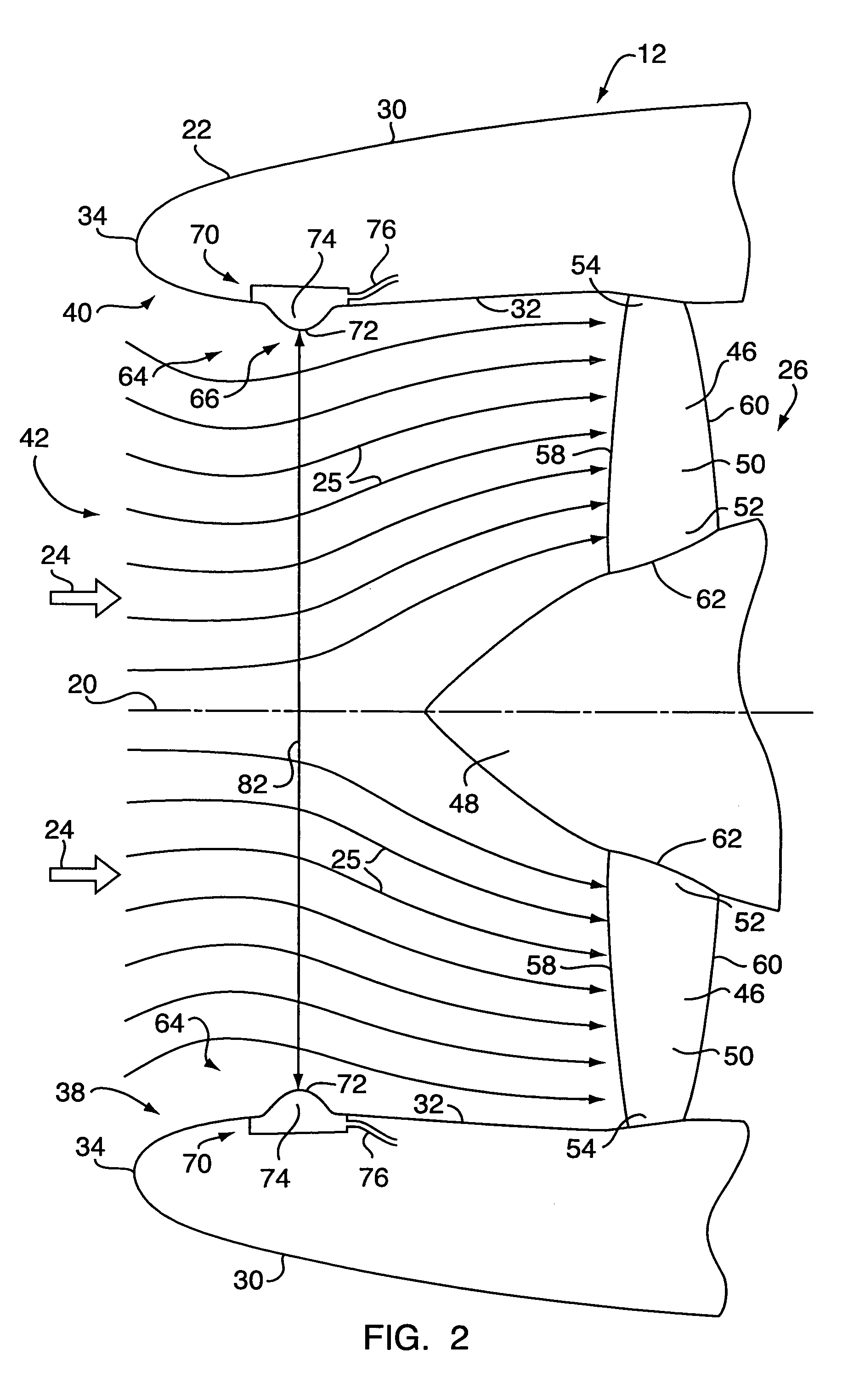
[0028] Referring to FIG. 1, a gas turbine engine 10 includes a fan section 12, a compressor 14, a combustor 16, and a turbine 18 centered around a central axis 20 and enclosed in a nacelle 22. Air 24 flows axially through the sections 12-18 of the engine 10 forming streamlines 25, as seen in FIG. 2. The fan section 12 includes a fan 26 which accelerates the air 24 to contribute to the overall thrust generated by the engine. As is well known in the art, the air 24, compressed in the compressor 14, is mixed with fuel and burnt in the combustor 16. Subsequently, the hot gases expand in the turbine 18 generating thrust to propel the engine 10 and to drive the turbine 18, which in turn drives the fan 26 and the compressor 14.

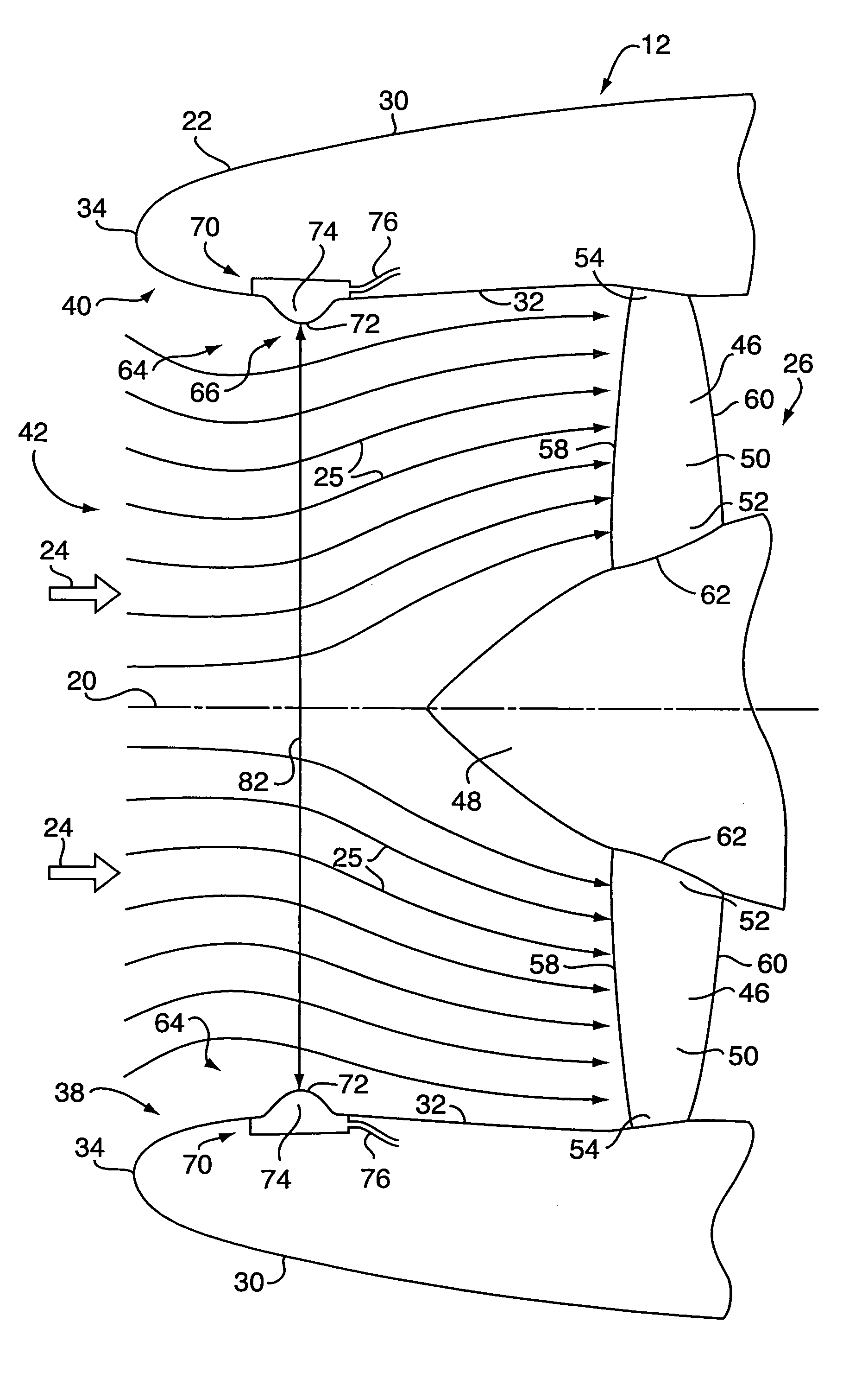
[0029] Referring to FIG. 2, the nacelle 22 includes an outer nacelle surface 30 and an inner nacelle surface 32 joined at a nacelle leading edge 34. The nacelle also includes a lower portion 38 and an upper portion 40. The inner nacelle surface 32 defines an inlet d...


PUM


Abstract

A gas turbine engine comprising a fan section, a compressor, a combustor and a turbine, includes a nacelle having an inner nacelle surface defining an inlet duct designed to reduce an inlet duct area of the inlet duct to increase acoustic attenuation. The gas turbine engine also includes a spinner, disposed forward of the fan section, that includes features to increase acoustic attenuation. In one embodiment of the present invention, the nacelle includes a nacelle contoured surface protruding radially inward from the inner nacelle surface to reduce the inlet duct area. In a further embodiment of the present invention, the spinner includes a spinner contoured surface for reducing the inlet duct area. In other embodiments, the nacelle and/or the spinner include an inflatable bladder, a SMA actuator, a fluidic actuator, or a combination thereof, selectively activated to increase acoustic attenuation during certain conditions of an aircraft.

Description

BACKGROUND OF THE INVENTION [0001] 1. Technical Field [0002] The present invention relates to gas turbine engines and, more particularly, to reduction of noise emanating therefrom. [0003] 2. Background Art [0004] In recent years, noise generated by flying aircraft has attracted attention and is now subject of various governmental regulations. Efforts need to be made to minimize annoyance to neighborhoods located in the path of departing and landing aircraft. The noise is especially disturbing during certain flight conditions such as takeoffs and landings of the aircraft. [0005] The aircraft noise is primarily generated by gas turbine engines propelling the aircraft. One major source of the noise generated by the gas turbine engine is the fan section. The fan generates tonal and broadband acoustic energy propagating outward of the engine through an inlet and through a bypass nozzle. [0006] Various considerations dictate design of the gas turbine engine that propels an aircraft. For e...

Claims


Application Information

Patent Timeline
Patent Type & Authority Applications(United States)
IPC IPC(8): F02C7/042F02C7/045F02C7/24F02K1/10F02K1/15F02K3/04
CPCB64D33/02B64D2033/0206B64D2033/0286F02C7/042F02C7/045Y10T137/0536
Inventor PRASAD, DILIPFENG, JINZHANGSABNIS, JAYANT S.
Owner UNITED TECH CORP
Why Eureka
Try Eureka