Eureka AIR delivers breakthrough ideas for toughest innovation challenges, trusted by R&D personnel around the world.

Device for acoustic treatment of the noise emitted by a turbojet

a technology for acoustic treatment and turbojets, which is applied in the direction of machines/engines, air-flow influencers, transportation and packaging, etc., can solve the problems of reducing the available area that can be treated acoustically with passive acoustic treatment panels, reducing the size of the nacelle, and reducing the available area for acoustic treatment. emitted, to achieve the effect of reducing the drawbacks and effectively a

Active Publication Date: 2013-11-12
SN DETUDE & DE CONSTR DE MOTEURS DAVIATION S N E C M A
View PDF30 Cites 23 Cited by
  • Summary
  • Abstract
  • Description
  • Claims
  • Application Information

AI Technical Summary

Benefits of technology

[0005]A main object of the present invention is to mitigate such drawbacks by proposing a passive acoustic treatment device that makes it possible to achieve effective attenuation of the noise emitted by a turbojet, in particular by its fan.
[0008]As a result, the noise leaving the acoustic treatment zone can be attenuated more strongly than is possible with panels presenting acoustic characteristics that remain uniform over their entire lengths. For constant treated surface areas, the acoustic treatment device of the invention thus makes it possible to increase acoustic attenuation at target frequencies by 20% to 40%. For constant acoustic attenuation, the acoustic treatment device of the invention makes it possible to reduce the bulk of the inner and outer panels.

Problems solved by technology

In the field of aviation, international and local regulations are becoming ever more severe concerning the sound nuisance produced by airplanes, and in particular the nuisance that can be attributed to turbojets.
Unfortunately, that trend leads to reducing the size of the nacelle, and thus to reducing the available area that can be treated acoustically with passive acoustic treatment panels.
Nevertheless, such a solution is not fully satisfactory in terms of reducing sound emission.

Method used


Image

  • Device for acoustic treatment of the noise emitted by a turbojet
  • Device for acoustic treatment of the noise emitted by a turbojet
  • Device for acoustic treatment of the noise emitted by a turbojet

Examples


Embodiment Construction

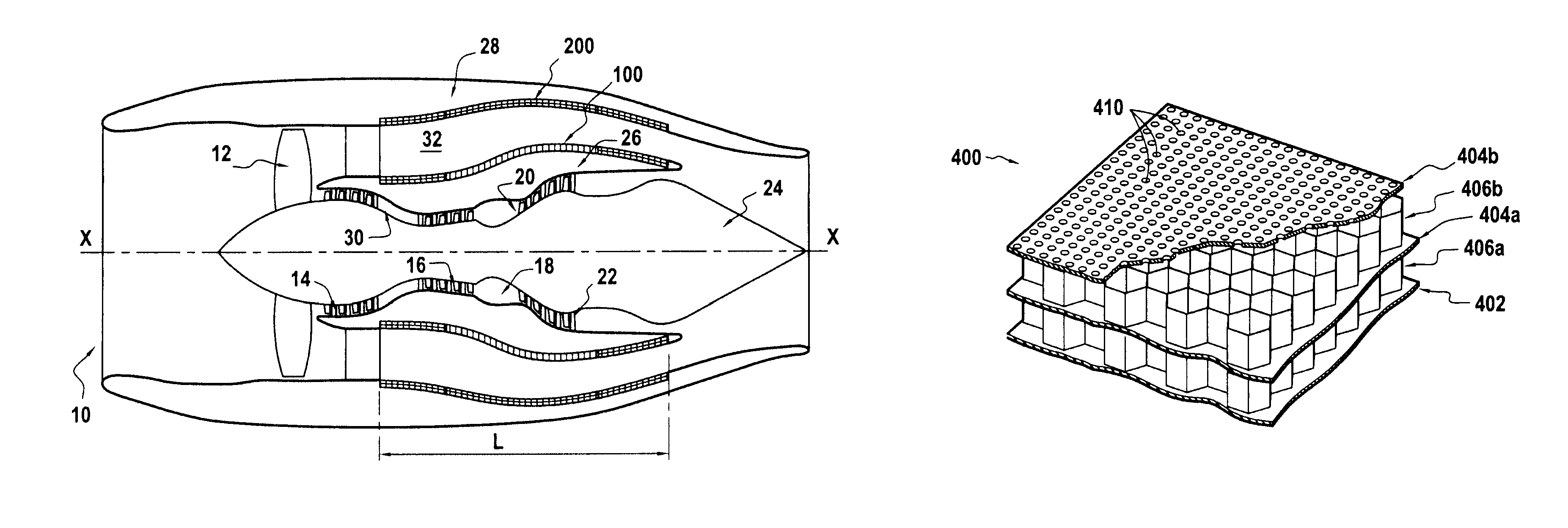
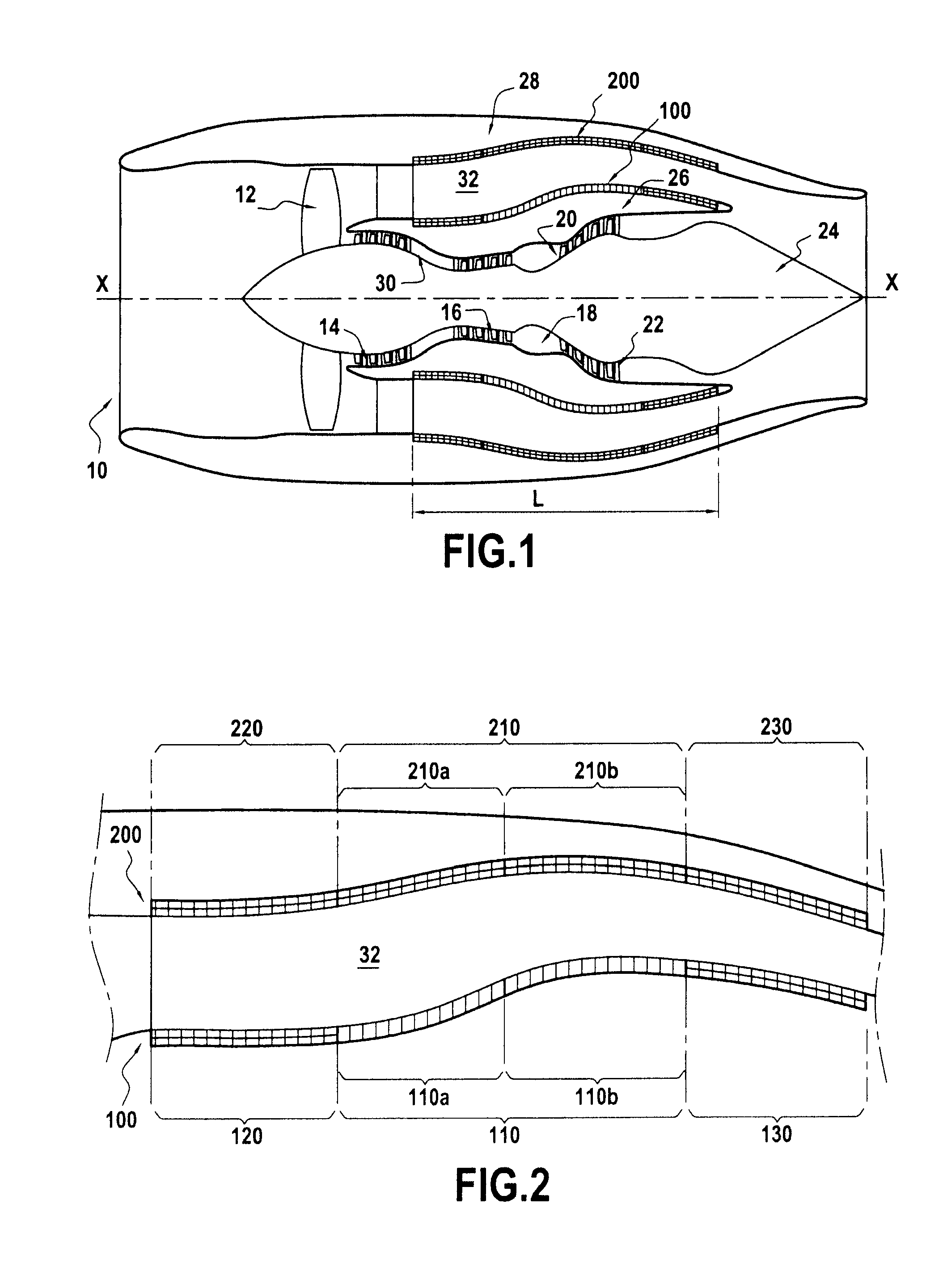
[0023]FIG. 1 shows an airplane turbojet 10 of the two-spool bypass type to which the invention applies in particular. Naturally, the invention also applies to other types of aircraft turbojet.

[0024]In known manner, going from upstream to downstream, the turbojet 10 comprises a fan 12, a low-pressure compressor 14, a high-pressure compressor 16, a combustion chamber 18, a high-pressure turbine 20, and a low-pressure turbine 22.

[0025]The turbojet 10 also includes an annular central core 24 centered on the longitudinal axis X-X of the turbojet, a primary cowl 26 surrounding the central body coaxially thereabout, and a secondary cover 28 surrounding the primary cowl, coaxially thereabout. The central core 24 and the primary cowl 26 define between them an annular channel 30 for passing a hot stream from the turbojet. Similarly, the primary and secondary cowls define between them an annular channel 32 for passing a cold stream from the turbojet, which channel is coaxial around the channel...


PUM


Abstract

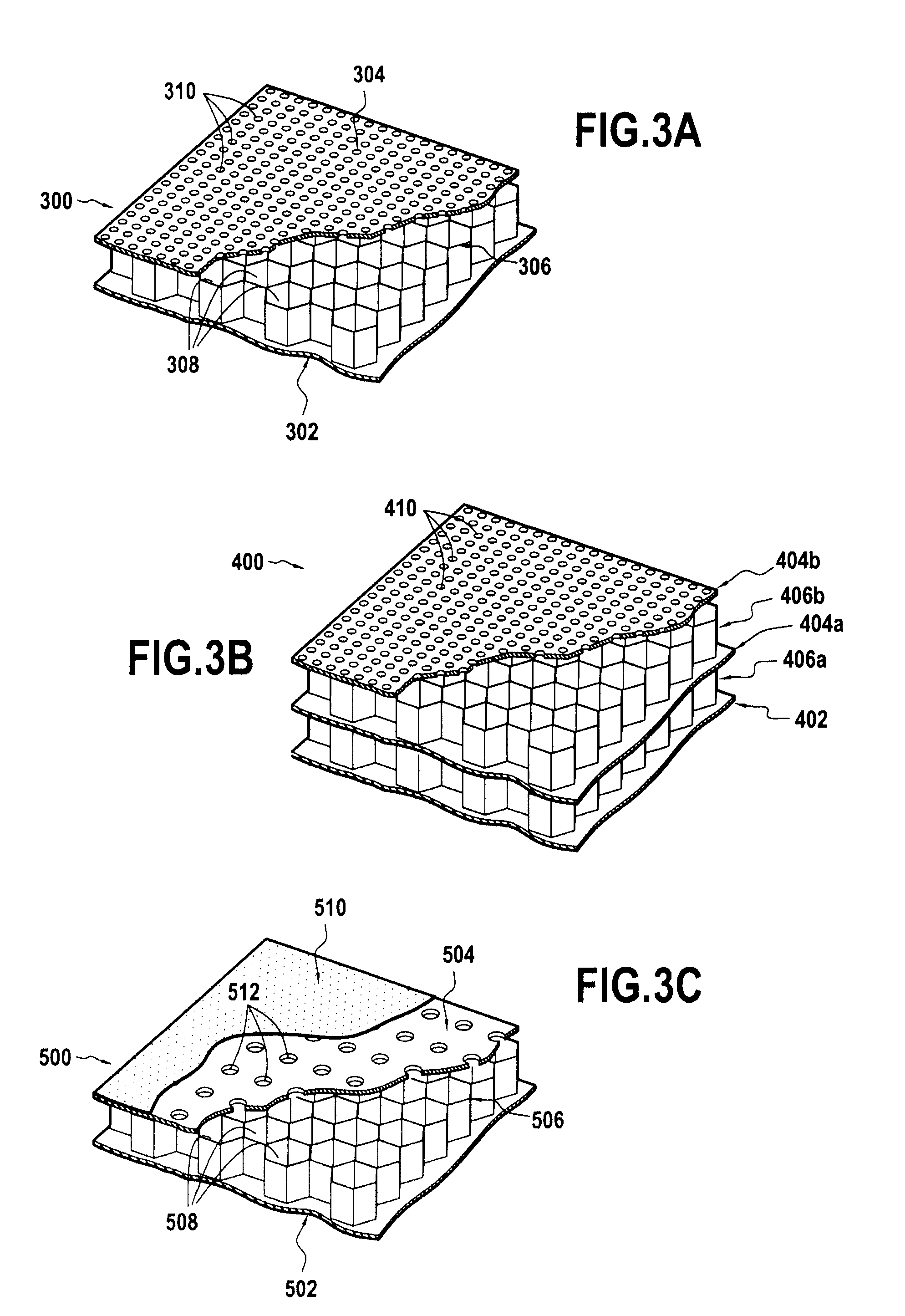
The invention provides a device for acoustical treatment of the noise emitted by a bypass turbojet comprising a primary cowl having in an outer surface an inner annular acoustic treatment panel and a secondary cowl including in an inner surface an outer annular acoustic treatment panel arranged facing the inner panel. The inner and outer panels include respective central panel portions facing each other and extending axially over a common predetermined length, the length of the central panel portions lying in the range one-fifth to four-fifths of the total length of the panels, and the ratio between the acoustic resistances of the central panel portions being not less than 2.

Description

BACKGROUND OF THE INVENTION[0001]The present invention relates to the general field of passive acoustic treatment dedicated to reducing the noise emitted by an aircraft turbojet.[0002]In the field of aviation, international and local regulations are becoming ever more severe concerning the sound nuisance produced by airplanes, and in particular the nuisance that can be attributed to turbojets. Engine manufacturers are thus being called on to reduce the noise from their turbojets, and in particular the fan noise that becomes the major component in the overall noise emitted by a turbojet.[0003]Some reduction in the fan noise of the turbojet can be obtained by modifying the shape and the section stacks of the fan blades. Nevertheless, having recourse to passive acoustic treatment panels remains the main element capable of attenuating such noise. Such panels are usually arranged in the engine nacelle, e.g. downstream from the fan around the outer surface of the primary cowl and the inne...

Claims


Application Information

Patent Timeline
Patent Type & Authority Patents(United States)
IPC IPC(8): B64C1/40
CPCF02C7/24F02K1/827F02K3/06
Inventor MARDJONO, JACKY NOVIJULLIARD, JACQUES MICHEL ALBERTRIOU, GEORGES JEAN XAVIER
Owner SN DETUDE & DE CONSTR DE MOTEURS DAVIATION S N E C M A
Why Eureka
Eureka Blog
Learn More