Containment Case Active Clearance Control Structure

a control structure and containment case technology, applied in the direction of machines/engines, mechanical equipment, liquid fuel engines, etc., can solve the problems of increased fuel consumption, efficiency and performance loss at the propulsion system,

Active Publication Date: 2020-03-26
GENERAL ELECTRIC CO
View PDF7 Cites 1 Cited by
  • Summary
  • Abstract
  • Description
  • Claims
  • Application Information

AI Technical Summary

Benefits of technology

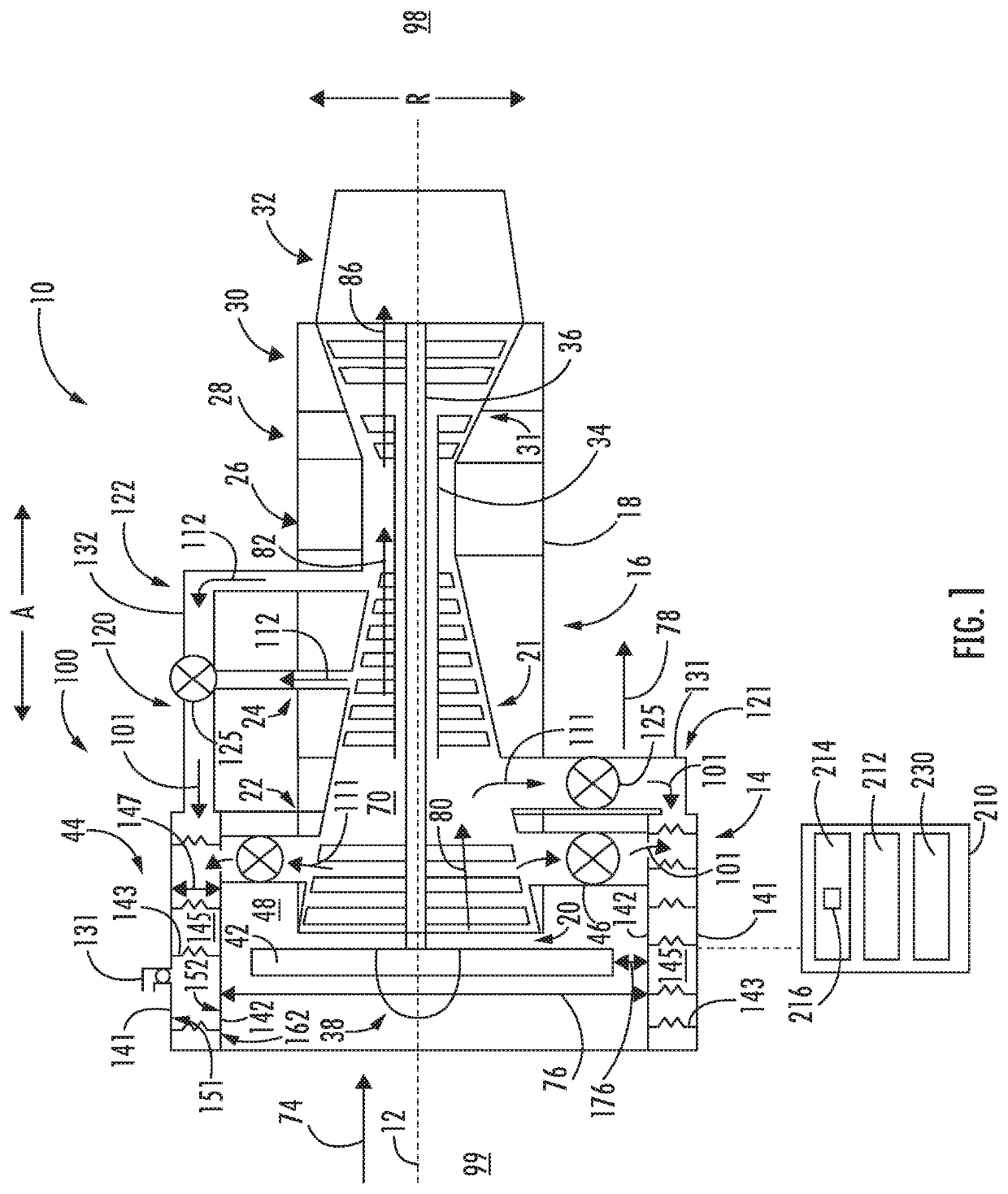
[0014]In still another embodiment, the operations further include flowing the flow of fluid from a first compressor of the compressor section to the flow passage of the casing; and increasing a propulsion system inlet area at the casing based on the flow of fluid from the first compressor.
[0015]In yet another embodiment, the operations further include flowing the flow of fluid from a second compressor of the compressor section to the flow passage of the casing; and decreasing a propulsion system inlet area at the casing based on the flow of fluid from the second compressor.

Problems solved by technology

Although such large clearances mitigate undesired contact, they further result in efficiency and performance losses (e.g., increased fuel consumption) at the propulsion system due to the larger clearances.

Method used


Image

  • Containment Case Active Clearance Control Structure
  • Containment Case Active Clearance Control Structure
  • Containment Case Active Clearance Control Structure

Examples


Embodiment Construction

[0028]Reference now will be made in detail to embodiments of the invention, one or more examples of which are illustrated in the drawings. Each example is provided by way of explanation of the invention, not limitation of the invention. In fact, it will be apparent to those skilled in the art that various modifications and variations can be made in the present invention without departing from the scope or spirit of the invention. For instance, features illustrated or described as part of one embodiment can be used with another embodiment to yield a still further embodiment. Thus, it is intended that the present invention covers such modifications and variations as come within the scope of the appended claims and their equivalents.

[0029]As used herein, the terms “first”, “second”, and “third” may be used interchangeably to distinguish one component from another and are not intended to signify location or importance of the individual components.

[0030]The terms “upstream” and “downstre...


PUM


Abstract

A propulsion system including a casing surrounding a fan rotor assembly is provided. The casing includes an outer layer material defining a first coefficient of thermal expansion (CTE) and an inner layer material. The casing further includes a spring member disposed between the outer layer material and the inner layer material coupling the outer layer material and the inner layer material. The spring member is coupled to each of the outer layer material and the inner layer material within a flow passage defined between the outer layer material and the inner layer material. The spring member defines a second CTE greater than the first CTE.

Description

FIELD[0001]The present subject matter relates generally to active clearance control systems for propulsion systems.BACKGROUND[0002]Propulsion systems, such as fan assemblies for gas turbine engines or electric propulsion systems, include fan rotors that may experience hard contact or rub a surrounding containment casing under certain adverse conditions. To avoid such undesired contact, a relatively large clearance may be defined between a tip of the fan blade and the containment casing. Although such large clearances mitigate undesired contact, they further result in efficiency and performance losses (e.g., increased fuel consumption) at the propulsion system due to the larger clearances.[0003]As such, there is a need for a containment casing that mitigates undesired contact with the fan rotor and improves efficiency and performance of the propulsion system.BRIEF DESCRIPTION[0004]Aspects and advantages of the invention will be set forth in part in the following description, or may b...

Claims


Application Information

Patent Timeline
Patent Type & Authority Applications(United States)
IPC IPC(8): F01D11/24F02C9/18F02C6/08F02K3/06
CPCF02C6/08F05D2220/36F02K3/06F05D2240/11F02C9/18F05D2260/52F01D11/24F02C9/00F02C7/18F04D29/522F04D29/584F01D21/045F02C7/047F05D2300/50212
Inventor KRAY, NICHOLAS JOSEPHJAIN, NITESHJAIN, MANOJ KUMAR
Owner GENERAL ELECTRIC CO
Why Eureka
Try Eureka