
Apparatus, system and method for pumping gaseous fluid

a gaseous fluid and apparatus technology, applied in the field of electric submersible pumps, can solve the problems of reducing the efficiency of the pump, the pump may experience a decrease in capacity or head (slipping), and the current submersible pump system is not suitable for pumping fluid with a high gas to liquid ratio, so as to reduce the pressure differential, minimize the fluid phase separation, and complete block the passage of other fluid through the impeller

Inactive Publication Date: 2014-01-30
HALLIBURTON ENERGY SERVICES INC
View PDF15 Cites 16 Cited by
  • Summary
  • Abstract
  • Description
  • Claims
  • Application Information

AI Technical Summary

Benefits of technology

The patent describes a method for pumping gaseous fluid from a well using a centrifugal pump. The method reduces phase separation of the fluid by minimizing pressure differential between the pressure side and the suction side of the pump's impeller vane. This is achieved by increasing the inlet area of the impeller and replacing the impeller vane with a truncated vane. This improves the pump's ability to pump gaseous fluid and reduces the likelihood of blockages and damage to the pump.

Problems solved by technology

Currently available submersible pump systems are not appropriate for pumping fluid with a high gas to liquid ratio.
If there is a sufficiently high gas volume fraction, typically around 10% to 15%, the pump may experience a decrease in efficiency and decrease in capacity or head (slipping).
If gas continues to accumulate on the suction side of the impeller it may entirely block the passage of other fluid through the impeller.
When this occurs the pump is said to be “gas locked” since proper operation of the pump is impeded by the accumulation of gas.
However it is often infeasible, costly or too time consuming to ascertain the correct type of pump and separator combination which might be effective for a particular well, and even if the correct arrangement is ascertained, the separator may not remove enough gas to prevent a loss in efficiency and / or prevent gas locking.
In the case of an electric submersible pump (ESP), a failure of the pump or any support components in the pump assembly can be catastrophic as it means a delay in well production and having to remove the pump from the well for repairs.
Currently available pump assemblies do not contain components to satisfactorily homogenize gas laden fluid and prevent gas locking This shortcoming decreases the efficiency and overall effectiveness of the pump assembly.

Method used


Image

  • Apparatus, system and method for pumping gaseous fluid
  • Apparatus, system and method for pumping gaseous fluid
  • Apparatus, system and method for pumping gaseous fluid

Examples


Embodiment Construction

[0029]An apparatus, system and method for pumping gaseous fluid will now be described. In the following exemplary description, numerous specific details are set forth in order to provide a more thorough understanding of embodiments of the invention. It will be apparent, however, to an artisan of ordinary skill that the present invention may be practiced without incorporating all aspects of the specific details described herein. In other instances, specific features, quantities, or measurements well known to those of ordinary skill in the art have not been described in detail so as not to obscure the invention. Readers should note that although examples of the invention are set forth herein, the claims, and the full scope of any equivalents, are what define the metes and bounds of the invention.

[0030]As used in this specification and the appended claims, the singular forms “a”, “an” and “the” include plural referents unless the context clearly dictates otherwise. Thus, for example, r...


PUM


Abstract

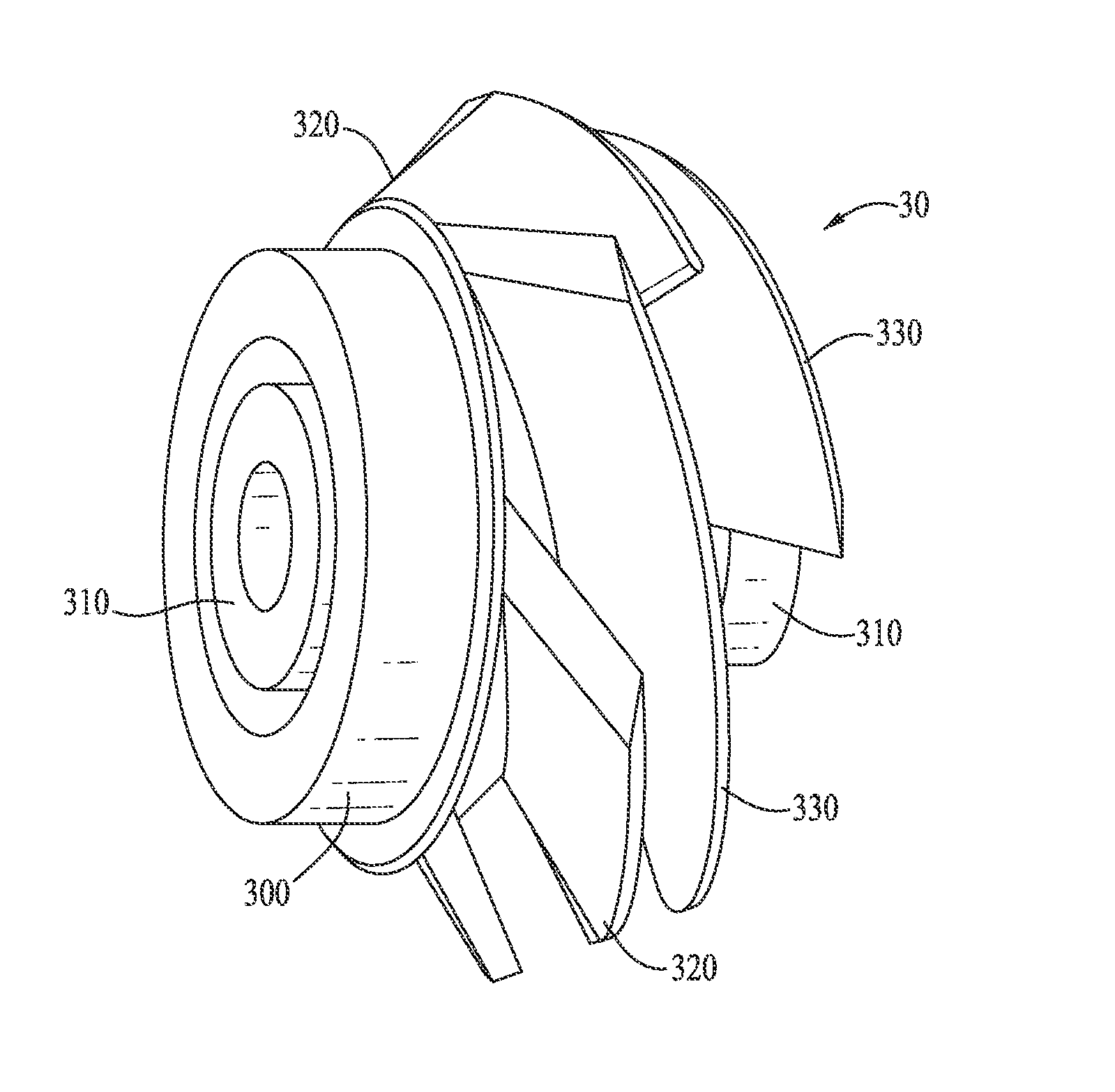
An apparatus, system and method for pumping gaseous fluid are described. The centrifugal pump of the invention homogenizes at least a portion of the gas and liquid contained in produced well fluid thereby improving the efficiency of the pump in electric submersible pump (ESP) applications and decreasing the downtime of the ESP system. The impeller of the invention comprises an increased inlet area. The centrifugal pump of the invention comprises a single shroud located on the bottom side of an impeller, an increased inlet area of the impeller and an increased clearance gap between the impeller and a diffuser. One or more truncated vanes extend substantially upstream from the single shroud, wherein each truncated vane sits at a mid-pitch location between untruncated vanes starting from the bottom side of the impeller.

Description

CROSS REFERENCE TO RELATED APPLICATIONS[0001]This application claims the benefit of U.S. Provisional Application No. 61 / 675,578 to Jayaram et al., filed Jul. 25, 2012 and entitled “APPARATUS, SYSTEM AND METHOD FOR PUMPING GASEOUS FLUID,” which is hereby incorporated by reference in its entirety.BACKGROUND OF THE INVENTION[0002]1. Field of the Invention[0003]Embodiments of the invention described herein pertain to the field of electric submersible pumps. More particularly, but not by way of limitation, one or more embodiments of the invention enable an apparatus, system and method for pumping gaseous fluid in electric submersible pump down-hole applications.[0004]2. Description of the Related Art[0005]Fluid, such as gas, oil or water, is often located in underground formations. In such situations, the fluid must be pumped to the surface so that it can be collected, separated, refined, distributed and / or sold. Centrifugal pumps are typically used in electric submersible pump applicati...

Claims


Application Information

Patent Timeline
Patent Type & Authority Applications(United States)
IPC IPC(8): F04D1/00
CPCF04D1/00F04D13/10F04D29/2238F04D31/00F04D1/04F04D29/18
Inventor JAYARAM, SHIVTETZLAFF, STEVEN KEITH
Owner HALLIBURTON ENERGY SERVICES INC
Learn More