
Speed Loop for Take-Off and Return by Single Pipeline Probe

Active Publication Date: 2019-01-03
MUSTANG SAMPLING
View PDF0 Cites 0 Cited by
  • Summary
  • Abstract
  • Description
  • Claims
  • Application Information

AI Technical Summary

Benefits of technology

[0034]The invention still further contemplates a combination of elements characterized by a multi-channel sample take-off and return probe, having a discharge port axially displaced from an entry port to minimize fluid flow disturbance in the pipeline process stream.
[0035]The present invention provides for use of a single pipeline probe for both take-off and sample return by in

Problems solved by technology

The use of such additional equipment also presents fu

Method used


Image

  • Speed Loop for Take-Off and Return by Single Pipeline Probe
  • Speed Loop for Take-Off and Return by Single Pipeline Probe

Examples


Example

DETAILED DESCRIPTION OF THE DRAWINGS

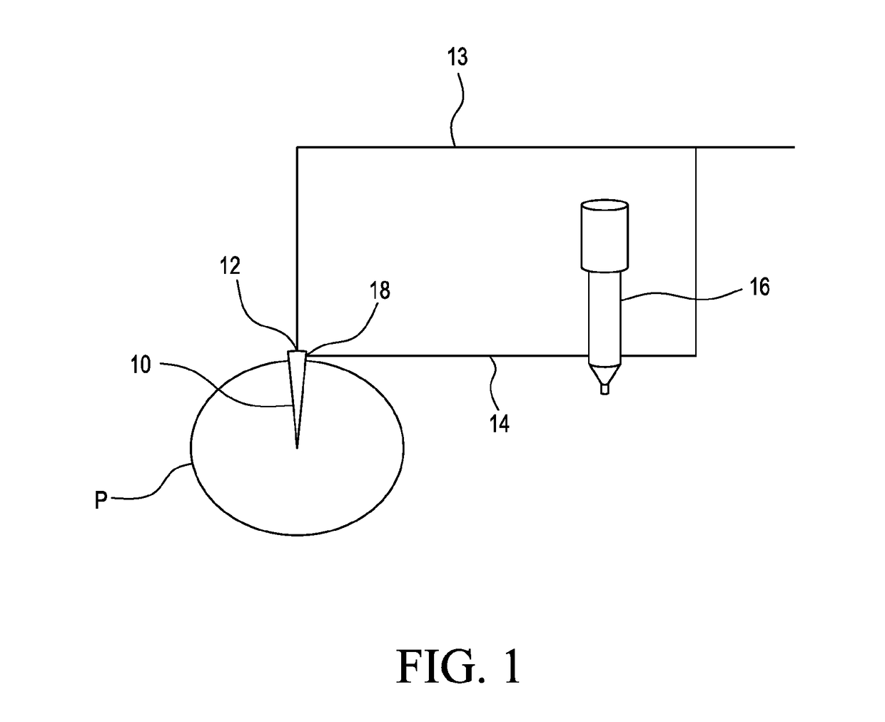
[0053]FIG. 1 illustrates a pipeline P having a sample probe 10 mounted therein. The sample probe 10 includes a take-off port 12 connected to a sample take-off line 13. Disposed at a point along the take-off line 13 and downstream of sample conditioning and / or analyzer equipment is a junction that forms a speed loop sample return line 14. The speed loop return line 14 features an in-line small volume pump 16 to increase the pressure of the returning excess extracted sample fluid prior to injection of the fluid into the return input port 18 of the sample probe 10.

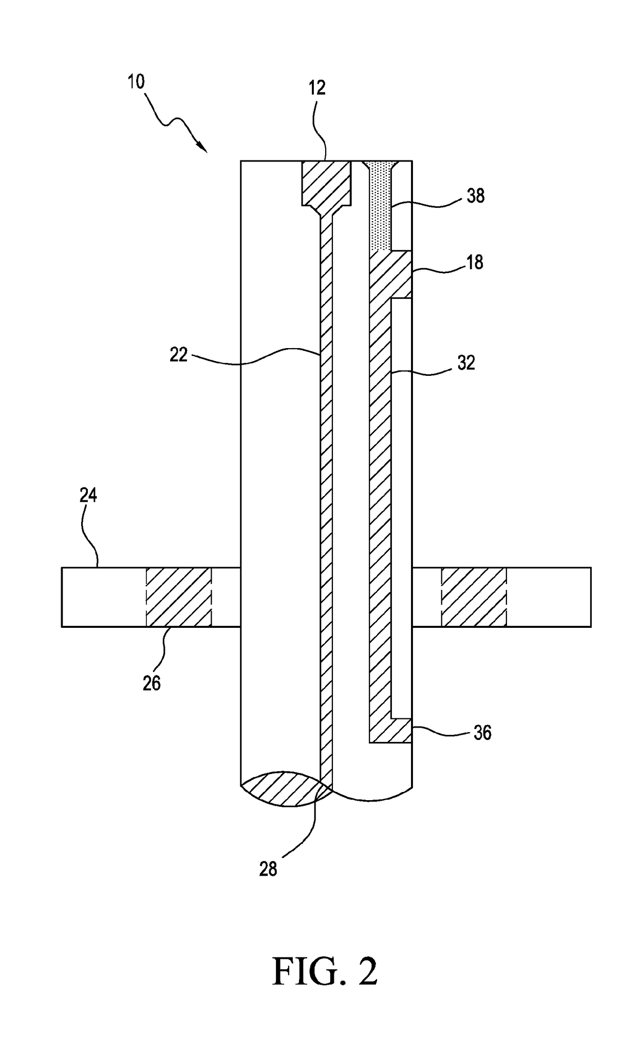
[0054]FIG. 2 illustrates details of an embodiment of an integrated, unitary sample probe 10 in accordance with the invention. The probe 10 features a stainless steel cylindrical body 22 with a length selected to project above a mounting flange (not illustrated) located on an underlying pipeline P. The probe 10 is removably secured to the pipeline mounting flange by direct bolting of probe f...


PUM


Abstract

A sample take-off system incorporating a small volume pump with a speed loop for pressurizing excess extracted sample for return into the process stream using a single multi-channel probe for both take-off and return of the excess extracted sample is illustrated and described.

Description

[0001]This PCT international application claims priority of U.S. application Ser. No. 15 / 252,686 filed Aug. 31, 2016 and U.S. provisional application Ser. No. 62 / 235,107 filed Sep. 30, 2015.TECHNICAL FIELD[0002]This invention relates to a system and method of establishing a speed loop that uses a single pipeline probe for sample take-off and fast-loop return of excess extracted sample to the pipeline process stream. The invention is particularly useful in the case of a low pressure gas source. A further aspect of the invention is to associate the speed loop with a pump to boost the pressure of low pressure sample gas to offset the take-off vacuum (i.e. suction pressure) and permit reinjection of excess sample fluid into the pipeline. Use of the invention avoids emissions by recirculating unused take-off fluid back into the pipeline source.BACKGROUND[0003]In the gas processing industry, excess sample fluid, often referred to as “boil off gas” or “BOG”, is disposed of by flaring or ot...

Claims


Application Information

Patent Timeline
IPC IPC(8): G01N1/20G01N1/14G01N1/42G01N33/00G01N33/22
CPCG01N1/2035G01N1/14G01N1/42G01N33/0011G01N33/225G01N2001/2064G01N2001/105G01N1/24G01N1/10G01N1/22G01N1/2247G01N1/44G01N1/02
Inventor ROLSTON, CLAUDE A.
Owner MUSTANG SAMPLING
Learn More