

Engine Controller
- Summary
- Abstract
- Description
- Claims
- Application Information
AI Technical Summary
Benefits of technology
Problems solved by technology
Method used
Image

Examples
Embodiment Construction
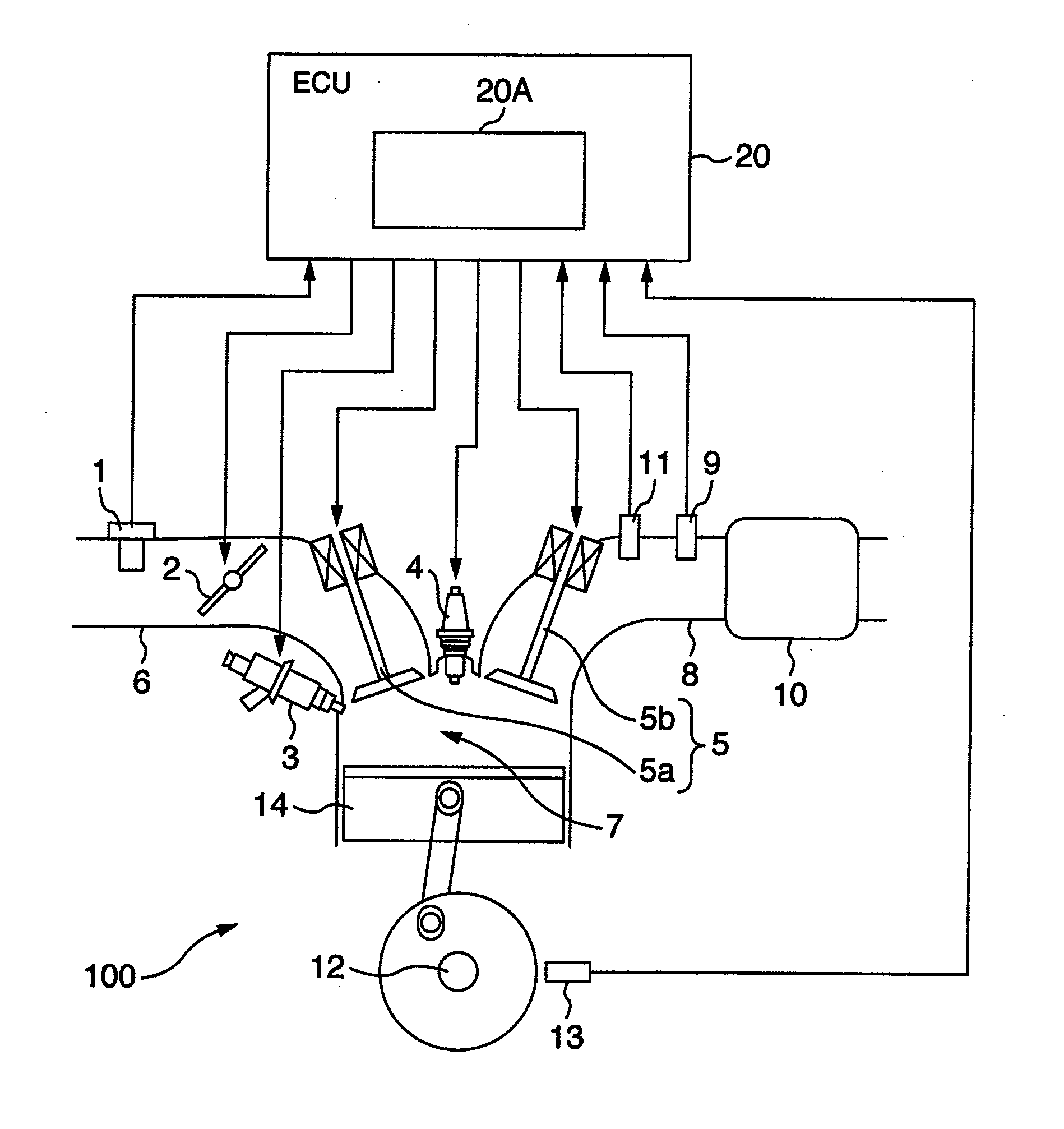
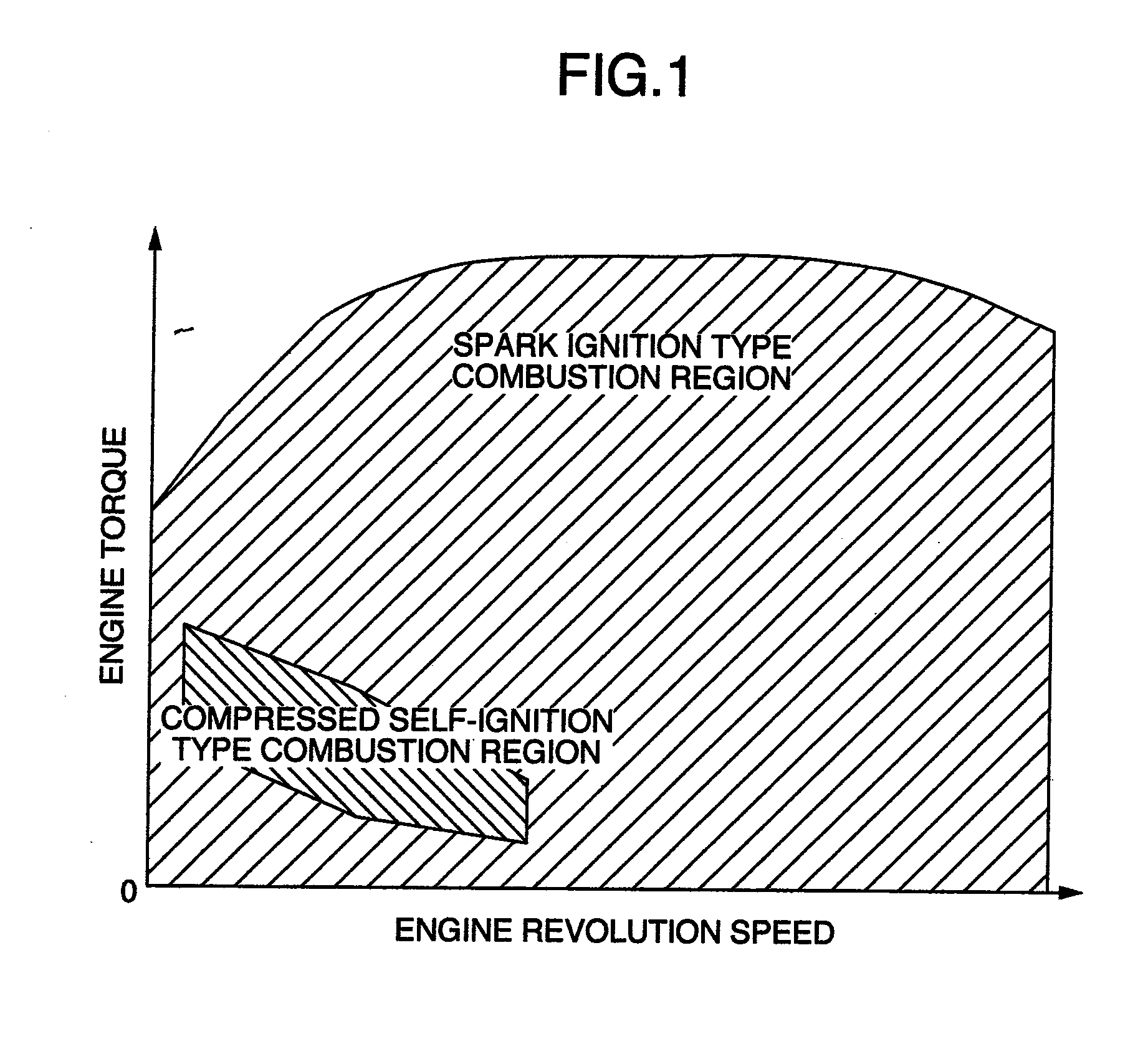
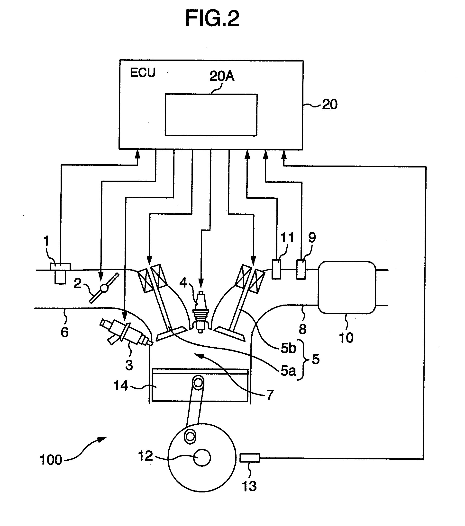
[0032]An engine controller of one embodiment according to the present invention is an engine controller capable of carrying out compressed self-ignition type combustion and spark ignition type combustion by switching them, and is characterized by providing, when switching a combustion mode from the compressed self-ignition type combustion to the spark ignition type combustion at a predetermined engine torque and a predetermined engine speed, a period 1 in which a throttle opening degree which is an opening degree of a throttle provided in an intake pipe of the internal combustion engine and capable of regulating an air amount flowing into a combustion chamber of the internal combustion engine is made smaller than a throttle opening degree 1 which is set when realizing the above engine torque and the above engine speed only by the spark ignition type combustion without carrying out combustion switching.
[0033]By such a configuration, the intake pipe pressure is quickly reduced when sw...
PUM
 Abstract
Description
Claims
Application Information