Method of determining valve leakage based on upstream and downstream temperature measurements

Active Publication Date: 2006-04-18
IMI VISION LTD
View PDF4 Cites 10 Cited by
  • Summary
  • Abstract
  • Description
  • Claims
  • Application Information

AI Technical Summary

Benefits of technology

[0011]In two-phase flow across the valve, the underlying principle upon which the leakage flow may be determined is based upon the condition that the liquid at the inlet of the valve (i.e., upstream of the valve) flashes to a mixture of liquid and vapor at the outlet of the valve (i.e., downstream of the valve). Under this condition, the flow downstream of the valve is at saturation temperature for its pressure. The underlying principle for determining valve leakage under such a condition is that any leakage of the valve will cause an increase in the pressure on the downstream side of the valve because of frictional resistance to flow in the

Problems solved by technology

The heat loss in the uninsulated portion of the bare pipe is th

Method used


Image

  • Method of determining valve leakage based on upstream and downstream temperature measurements
  • Method of determining valve leakage based on upstream and downstream temperature measurements
  • Method of determining valve leakage based on upstream and downstream temperature measurements

Examples


Example

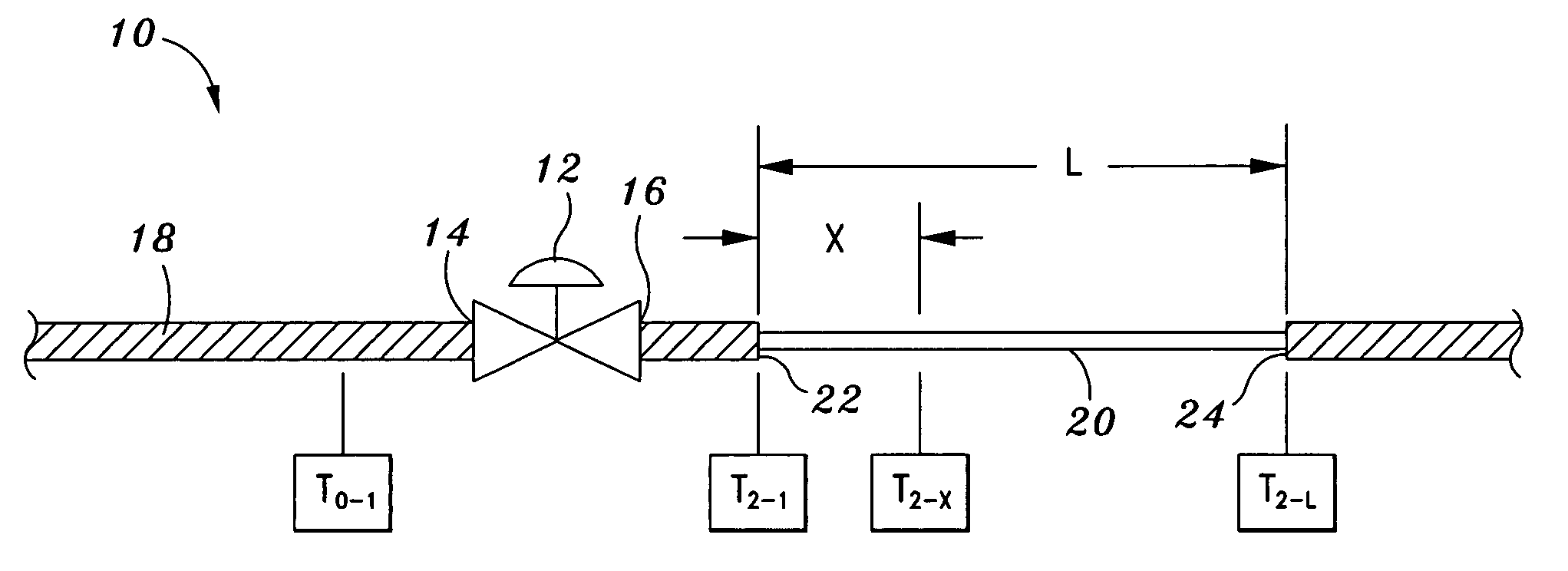
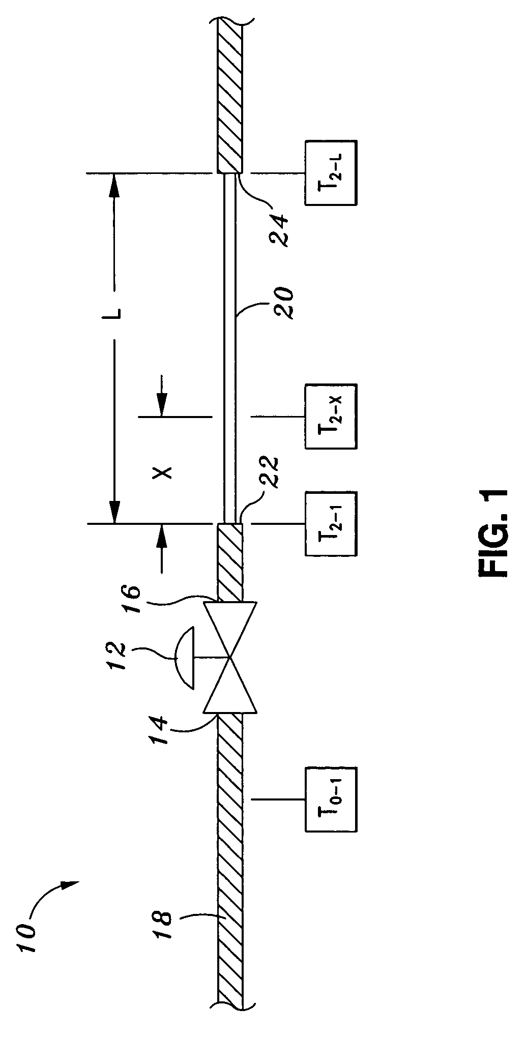
[0019]Referring now to the drawings wherein the showings are for purposes of illustrating preferred embodiments of the present invention only, and not for purposes of limiting the same, FIG. 1 illustrates a piping system 10 arrangement having a valve 12 interposed between a first pipe section 18 and a second pipe section 20. As can be seen, the valve 12 has an inlet 14 and an outlet 16. The piping system 10 of FIG. 1 is arranged for detecting leakage of the valve 12 and measuring the leakage flow rate Wleak of the valve 12 when the fluid flows through the valve 12 in a single-phase flow of a gas or steam. In single-phase flow, the underlying principle upon which the leakage of the valve 12 may be detected and measured is that the heat loss across a length of bare pipe located downstream of the valve 12 causes a decrease in the temperature of the leakage flow.

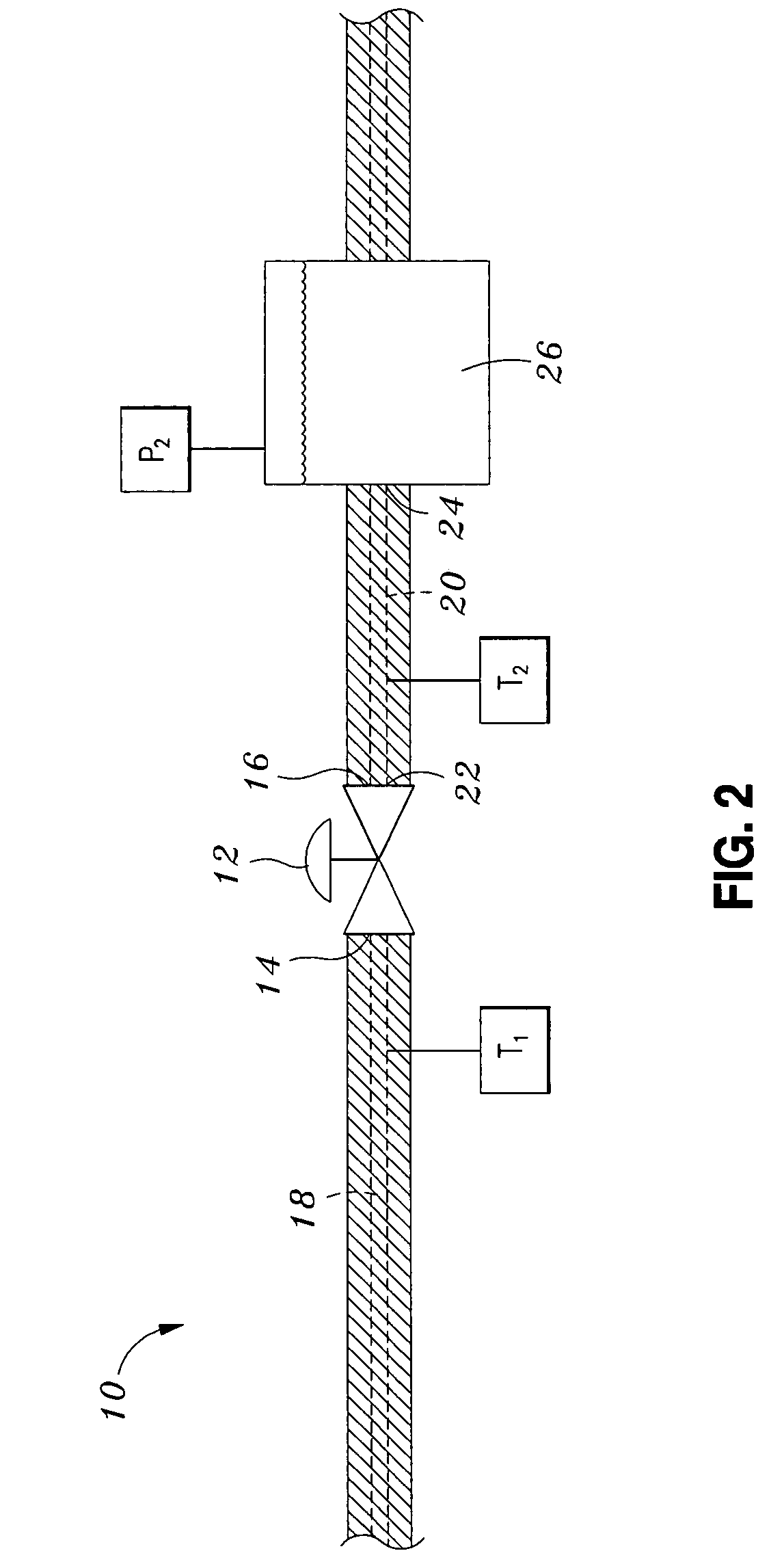
[0020]The piping system 10 of FIG. 2 is arranged for measuring the leakage flow rate Wleak through the valve 12 when the fluid...


PUM


Abstract

Disclosed is a method for measuring leakage flow rate of a valve wherein fluid flows through the valve in a single-phase flow of a gas or steam. The underlying principle upon which the leakage flow rate may be determined is that the heat loss across a length of bare pipe located downstream of the valve causes a decrease in the temperature of the leakage flow. Also disclosed is a method for measuring the leakage flow rate when the fluid passing through the valve transitions from a liquid-phase flow into a two-phase flow of liquid and steam. In two-phase flow, the underlying principle upon which the leakage flow rate may be determined is that any leakage of the valve will cause an increase in the pressure on the downstream side of the valve because of frictional resistance to flow in the downstream piping which corresponds to an increase in temperature thereof.

Description

CROSS-REFERENCE TO RELATED APPLICATIONS[0001]This application claims priority to U.S. Provisional Application No. 60 / 465,309, filed Apr. 25, 2003.STATEMENT RE: FEDERALLY SPONSORED RESEARCH / DEVELOPMENT[0002](Not Applicable)BACKGROUND OF THE INVENTION[0003]Control valves play a major role in the operating efficiency of power generating systems. Such control valves must be capable of regulating the flow of fluid under extreme thermodynamic conditions. High-temperature fluid flowing through the control valve may be under high pressure and may be flowing at a high velocity. Control valves must be capable of regulating the flow of single-phase fluid where the fluid is in a gaseous state. Control valves must also be capable of regulating the flow of two-phase fluid wherein a liquid phase of the fluid at the valve inlet flashes into a mixture of liquid and steam at the valve outlet. Regardless of the form of the fluid passing through the control valve, tight shutoff of the control valve mus...

Claims


Application Information

Patent Timeline
IPC IPC(8): G01F17/00G01F23/00F17D5/02G01M3/00
CPCG01M3/002F17D5/02
Inventor SHERIKAR, SANJAY V.
Owner IMI VISION LTD
Why Eureka
Try Eureka