
Heated regulator with removable heat inducer and fluid heater and methods of use

Active Publication Date: 2005-12-15
WELKER ENG
View PDF19 Cites 4 Cited by
  • Summary
  • Abstract
  • Description
  • Claims
  • Application Information

AI Technical Summary

Benefits of technology

[0003] The heated regulator has a body that defines a heating chamber sized and arranged to receive a removable heat inducer. A heat tube penetrates at least a portion of the heating chamber and contains an electrical heating element. When electrical current flows through the heating element, it heats up which warms the heat tube and the heat inducer. A fluid contacts the heat inducer and flows through the heating chamber to raise the temperature of the fluid. The heated regulator may be used to prevent condensation of gases prior to entering instrumentation systems. The heated regulator can also be used to heat fluids and to vaporize liquids prior to gas analysis. The removable heat inducer can have various shapes and designs. On one embodiment, there are threads formed on the outside surface, which when heated expand and engage the inside wall of the

Problems solved by technology

The pipeline can be taped and a sample drawn directly therefrom, however the pressure of the fluid in a pipeline is often too high for use in analyzing or measuring instruments.
This reduction in pressure may also cause a drop in temperature due to the Joule-Thomson effect which can also cause condensation of gases.
Condensation is undesirable for gas entering instrumentation systems.
The problem with many of these prior art heated regulators is that they do a poor job of actually heating the gas.

Method used


Image

  • Heated regulator with removable heat inducer and fluid heater and methods of use
  • Heated regulator with removable heat inducer and fluid heater and methods of use
  • Heated regulator with removable heat inducer and fluid heater and methods of use

Examples


Embodiment Construction

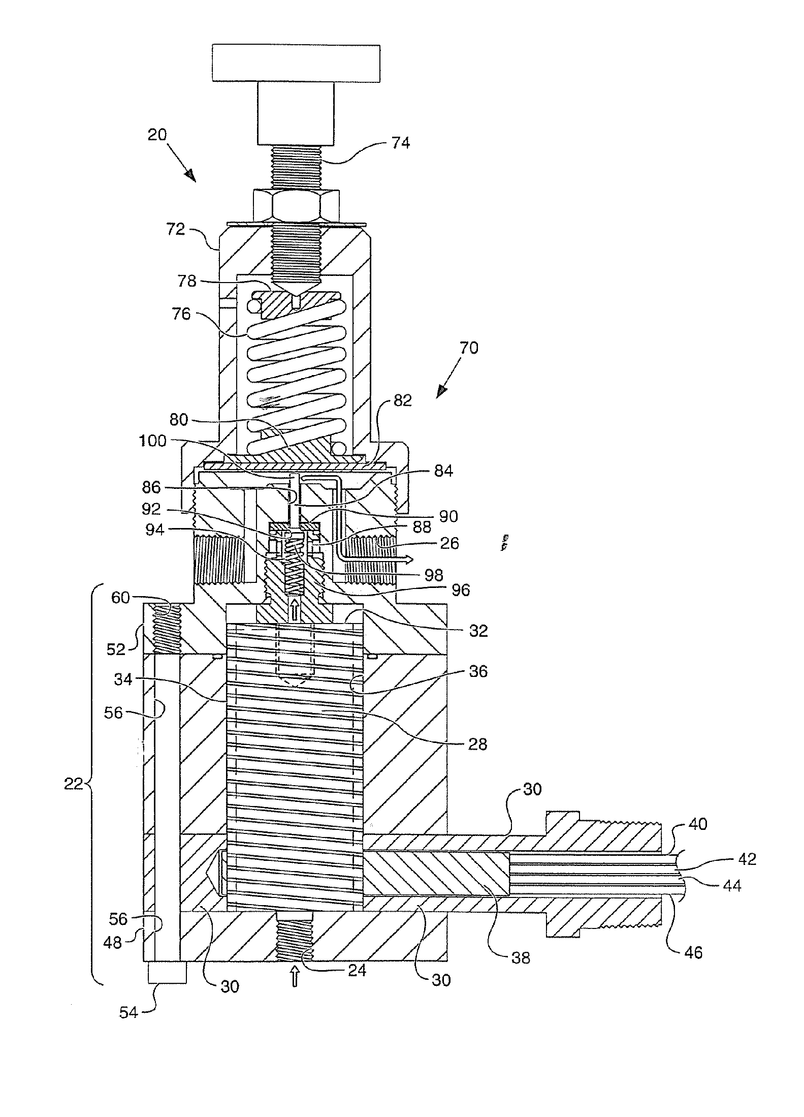
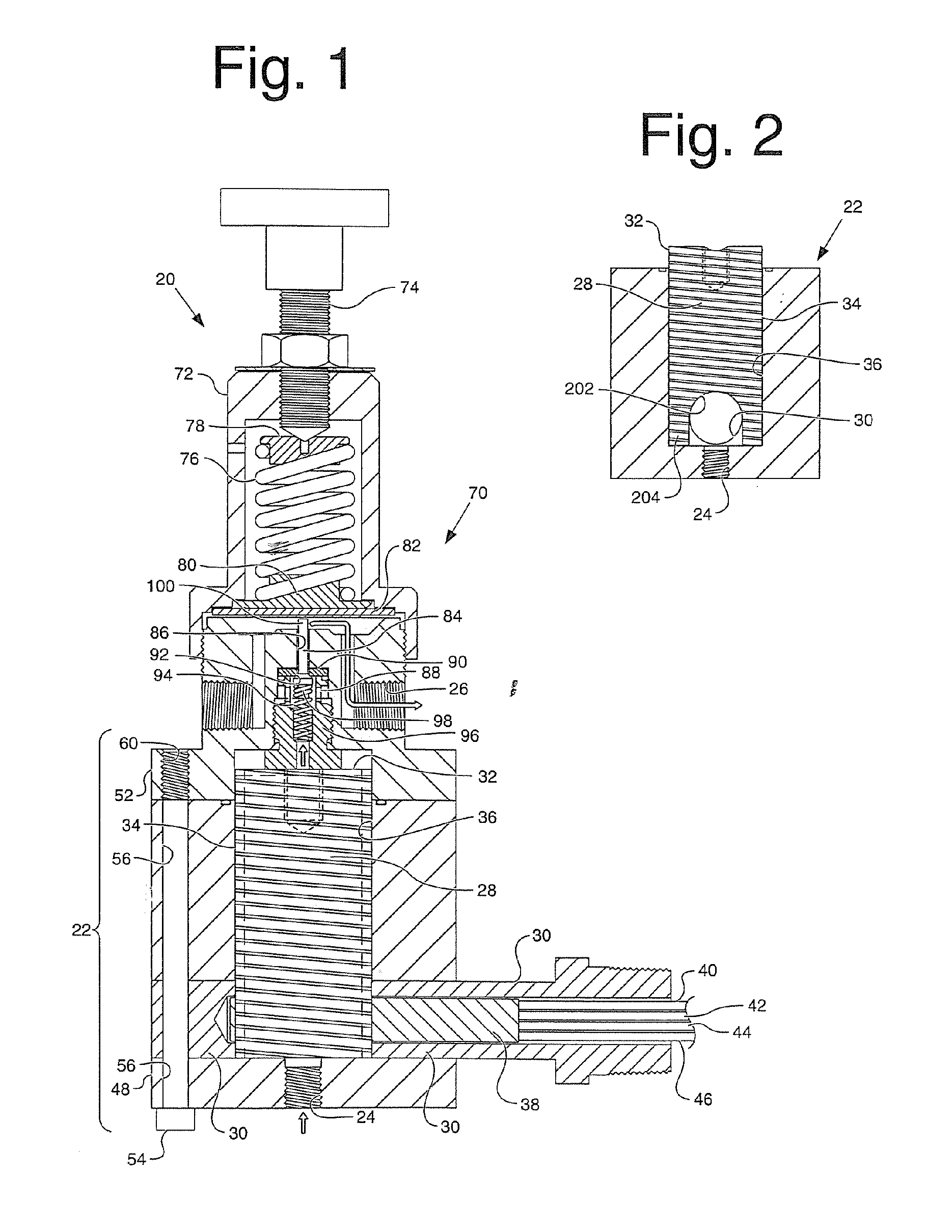
[0013]FIG. 1 is a section view of the heated regulator generally identified by the numeral 20. The regulator body 22 defines an inlet 24 and an outlet 26, which may also be referred to as the regulated pressure outlet. The body 22 defines a heating chamber 28. The removable heat inducer 32 is sized and arranged to fit inside the heating chamber with enough clearance to allow easy insertion and removal. However, the clearance should also be small enough so portions of the outside surface 34 of the heat inducer will contact the inside surface 36 of the heating chamber when both are heating to operating temperatures. Applicant has found that a clearance of about 0.005 to about 0.010 inches is suitable for this apparatus using an aluminum removable heat inducer 32.

[0014] The heating element 38 is connected to multiple conductors 40, 42, 44 and 46. The conductors connect to a source of electrical power, not shown and control instrumentation, not shown. In one embodiment a 150 watt heati...


PUM


Abstract

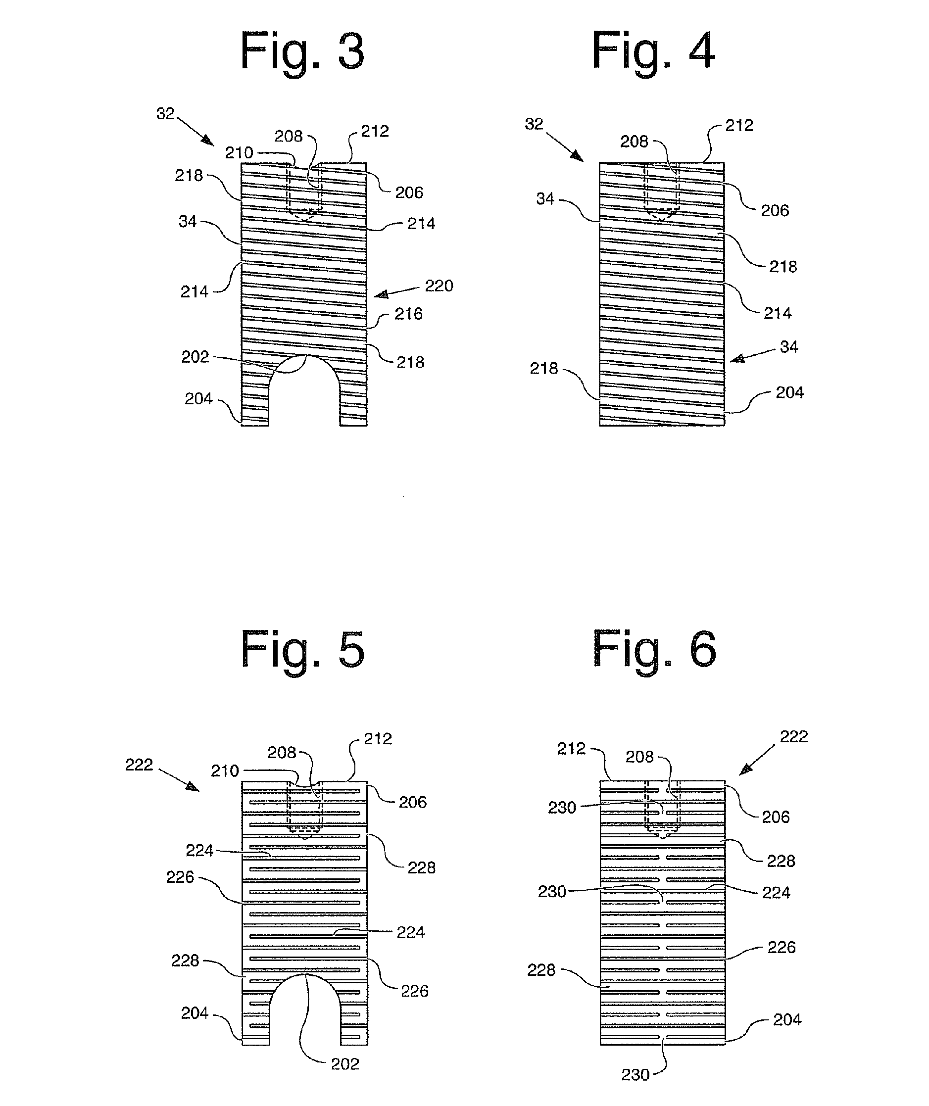
A removable heat inducer may be used in either a heated regulator or a fluid heater. The removable heat inducer has various embodiments. In one embodiment, helical threads are formed on the outside surface of the inducer. The inducer expands when heated causing the crest of the threads to come into contact with the inside surface of a heating chamber to form a spiral fluid passageway which promotes better heat exchange between the fluid and the heating element. In a first alternative embodiment of the inducer, a series of walled partitions and slots are formed on the outside surface of the inducer, which likewise expand and contact the inside surface of the heating chamber to form a dead head flow passageway. Again, the purpose of the passageway is to promote efficient heat exchange. In a second alternative embodiment of the removable heat inducer, a plurality of rods are placed in the heating chamber to promote heat exchange. The spaces between the rods form passageways for the fluid. The removable heat inducer may be used in a heated regulator or a fluid heater.

Description

BACKGROUND OF THE INVENTION [0001] It is often desirable in the natural gas, petrochemical and oil industries to withdraw samples directly from pipelines, vessels or process for analysis or measurement of the fluid. Various instruments are used for this purpose, such as calorimeters, gravitometers, and hydrogen sulfide analyzers. The pipeline can be taped and a sample drawn directly therefrom, however the pressure of the fluid in a pipeline is often too high for use in analyzing or measuring instruments. Pipelines carry natural gas at pressures as great as 5,000 pisg, while many gas analyzing instruments cannot use samples at greater than 100 psig. Regulators are used to step down pipeline pressures to instrument pressures. This reduction in pressure may also cause a drop in temperature due to the Joule-Thomson effect which can also cause condensation of gases. Condensation is undesirable for gas entering instrumentation systems. [0002] Therefore, many regulators are heated to count...

Claims


Application Information

Patent Timeline
IPC IPC(8): F24H1/10F24H3/02G01N30/04
CPCF24H1/102G05D16/0663
Inventor PEEBLES, TRACY DEANGREEN, THOMAS S.
Owner WELKER ENG
Learn More