Pointing device

a pointing device and pointing technology, applied in instruments, cathode-ray tube indicators, computing and other directions, can solve the problems of difficult application of ball mouse and optical mouse to portable electronic devices, user disassembly and replacement of pointing devices, and user's inability to use tsps

Inactive Publication Date: 2005-12-15
MOBISOL
View PDF8 Cites 74 Cited by
  • Summary
  • Abstract
  • Description
  • Claims
  • Application Information

AI Technical Summary

Benefits of technology

[0030]100, 440: light emitting means110: contact subject120, 400: image-formation means130, 150: conversion means140: motion detector150: operation means160: casing170: hole180: transparent plate190, 405: light guide structure300: portable electronic device310: pointing device320: mark330: selection button350: contact sensor360: control part410: housing420: printed circuit board430: cover500: pointing device module510: contact area520: switch530: screen540: pointer

Problems solved by technology

However, these conventional pointing devices have several disadvantages.
In addition, users are disabled to use the TSP whenever the sharp-end tool is mislocated or not available.
The ball mouse and optical mouse are difficult to be applied to portable electronic devices of small size because of the intrinsic limitations of their movement structure.
However, the above-mentioned prior art has a problem that it is restricted to a ball mouse because the pointing device employs a ball installed in a concave groove of a housing.
In addition, the ball is protruded outside from the lower side of the portable terminal, thereby causing inconvenience in use.

Method used


Image

  • Pointing device
  • Pointing device
  • Pointing device

Examples


Embodiment Construction

[0031] Reference will now be made in detail to the preferred embodiments of the present invention, examples of which are illustrated in the accompanying drawings.

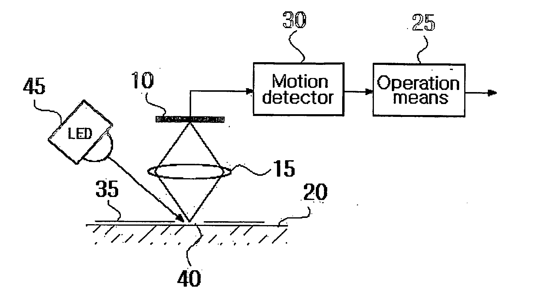
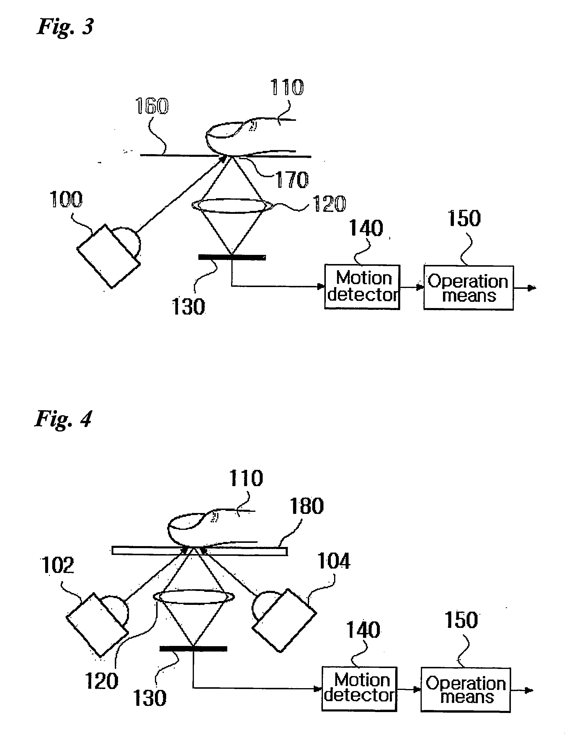
[0032]FIG. 3 is a schematic diagram of a pointing device in accordance with an embodiment of the present invention. Referring to FIG. 3, the pointing device of the present invention calculates the distance and direction for a pointer to be moved by acquiring and analyzing an image formed by light that is transmitted from a light emitting means (100) to a contact subject (110). This method presents a similar effect to that of an optical mouse, which moves on the fixed surface of a desk or a flat part. Here, the pointer means an indicator on a screen of display device, which is moved by a pointing device such as a mouse.

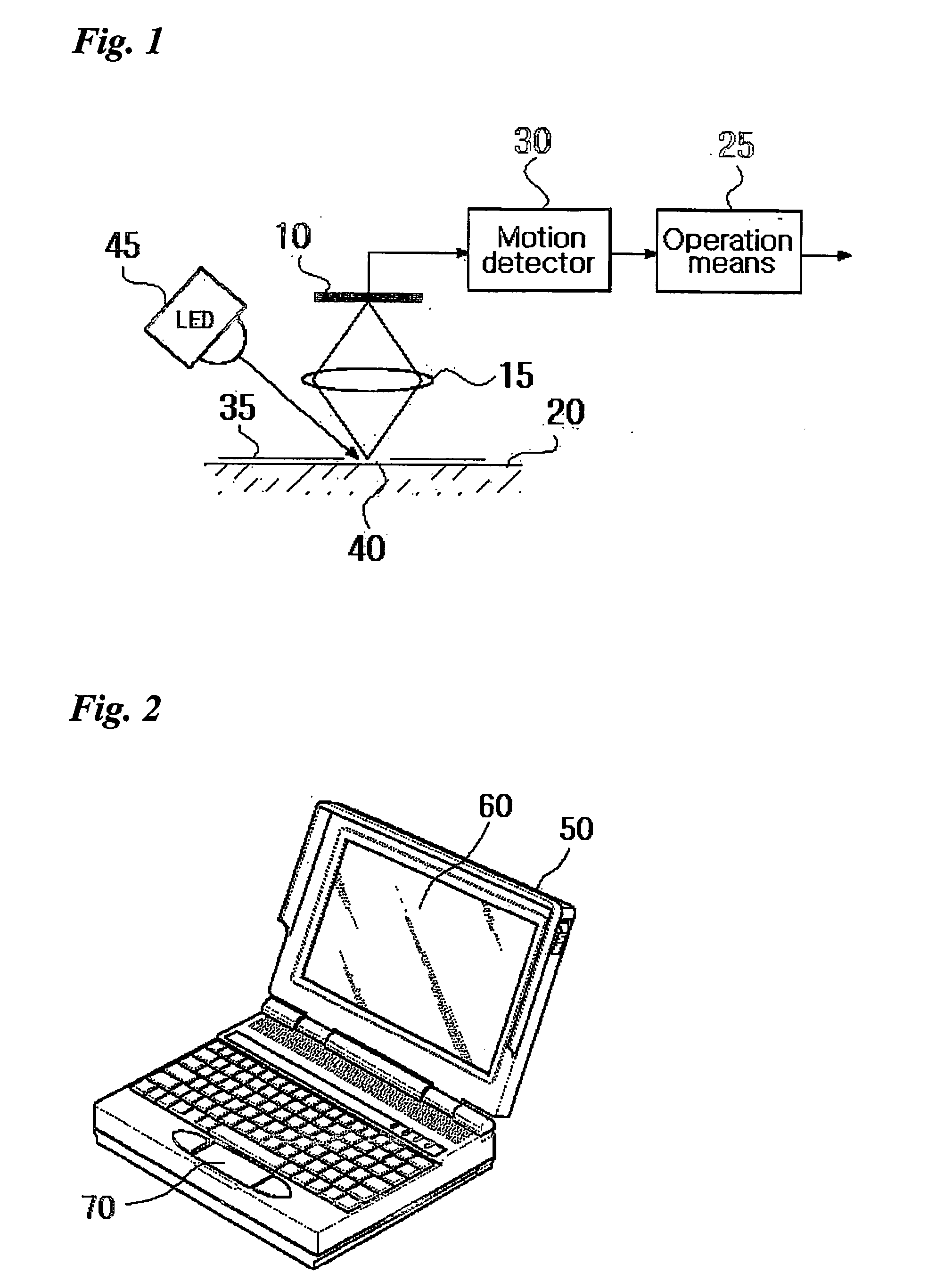
[0033] Such a pointing device is mounted on a portable electronic device and acquires changing images. In other words, a user can conveniently control a pointer on the screen of portable electronic device us...


PUM


Abstract

A pointing device to operate a portable electronic device using a finger is disclosed. The pointing device comprises a light emitting means for illuminating a subject; a hole through which light from the light emitting means is transmitted; an image-acquisition area for taking an image of the subject from the transmitted light; an image-formation means for forming an image by focusing the light reflected from the image-acquisition area; a conversion means for converting the image formed by the image-formation means into an electric signal; and an operation means for detecting the change of the image and calculating the amount of the change using the electric signal output from the conversion means. The subject is preferably the surface of a finger, a lattice, or any perceivable pattern. The pointing device can be embodied on portable electronic devices such as cellular phones and PDAs because it is small in size.

Description

TECHNICAL FIELD [0001] The present invention relates to a pointing device and, more particularly, to a pointing device to operate a handheld terminal using a finger. BACKGROUND ART [0002] Pointing devices generally include XY tablets, trackballs and mouse that are used for stationary devices such as desktop computers, and touch screen panels (hereinafter referred to as “TSPs”) and touch pads that are used for portable electronic devices such as notebook computers. [0003] The XY tablet is a means for calculating position variation of the magnetic field, which is generated by the flow of electric current, with a separate magnetic field sensor. In detail, electric currents are successively applied to a lattice consisting of two-dimensional conductors toward X or Y direction to generate a magnetic field. The XY tablet comprises a magnetic field sensor connected with an XY tablet body. [0004] The trackball includes an appropriate fixing member to prevent a rolling spherical ball from get...

Claims


Application Information

Patent Timeline
Patent Type & Authority Applications(United States)
IPC IPC(8): G06F3/033G06F3/03G09G5/00
CPCG06F3/0317G06F3/03
Inventor JUH, SUNG CHULKIM, YOON SOOOH, SEUNG HAICHO, KYU DEUKKIM, TAE WOOYONG, DONG JUNGJO, JAE YOUNG
Owner MOBISOL
Why Eureka
Try Eureka