Monitoring system of specific area

a technology of monitoring system and specific area, applied in the direction of television system, selective content distribution, instruments, etc., to achieve the effect of drastically reducing labor or maintenance costs

Inactive Publication Date: 2005-12-15
DENARO
View PDF10 Cites 36 Cited by
  • Summary
  • Abstract
  • Description
  • Claims
  • Application Information

AI Technical Summary

Benefits of technology

[0007] According to this characteristic, when the monitor terminal becomes close to another monitor terminal, the proximity detecting means detects the proximity to transmit it to the monitor image switching means, the monitor image switching means switches the monitor images to be transmitted to the monitor to the monitor image of another monitor terminal, and thus the trouble of switching the monitor image to another monitor terminal can be solved.
[0009] With this method, a plurality of monitor terminals can share the moving path, and the monitoring system can be built inexpensively and in a short period comparing to a case of installing plurality of moving paths.
[0011] With this configuration, communication between the moving units and an external monitor can be formed simply via the fixed unit, and the non-contact communication using no cable or the like is employed, so that wear of such cable caused by movement does not occur and labor or cost for maintenance can be drastically reduced.

Problems solved by technology

In this case, there existed a problem that when a first monitor camera moves and comes into contact with another monitor camera, it cannot move forward on the moving path beyond the monitor camera that came into contact, and a monitor image must be switched from the first monitor camera to another monitor camera every time, which was bothersome.

Method used


Image

  • Monitoring system of specific area
  • Monitoring system of specific area
  • Monitoring system of specific area

Examples


embodiment

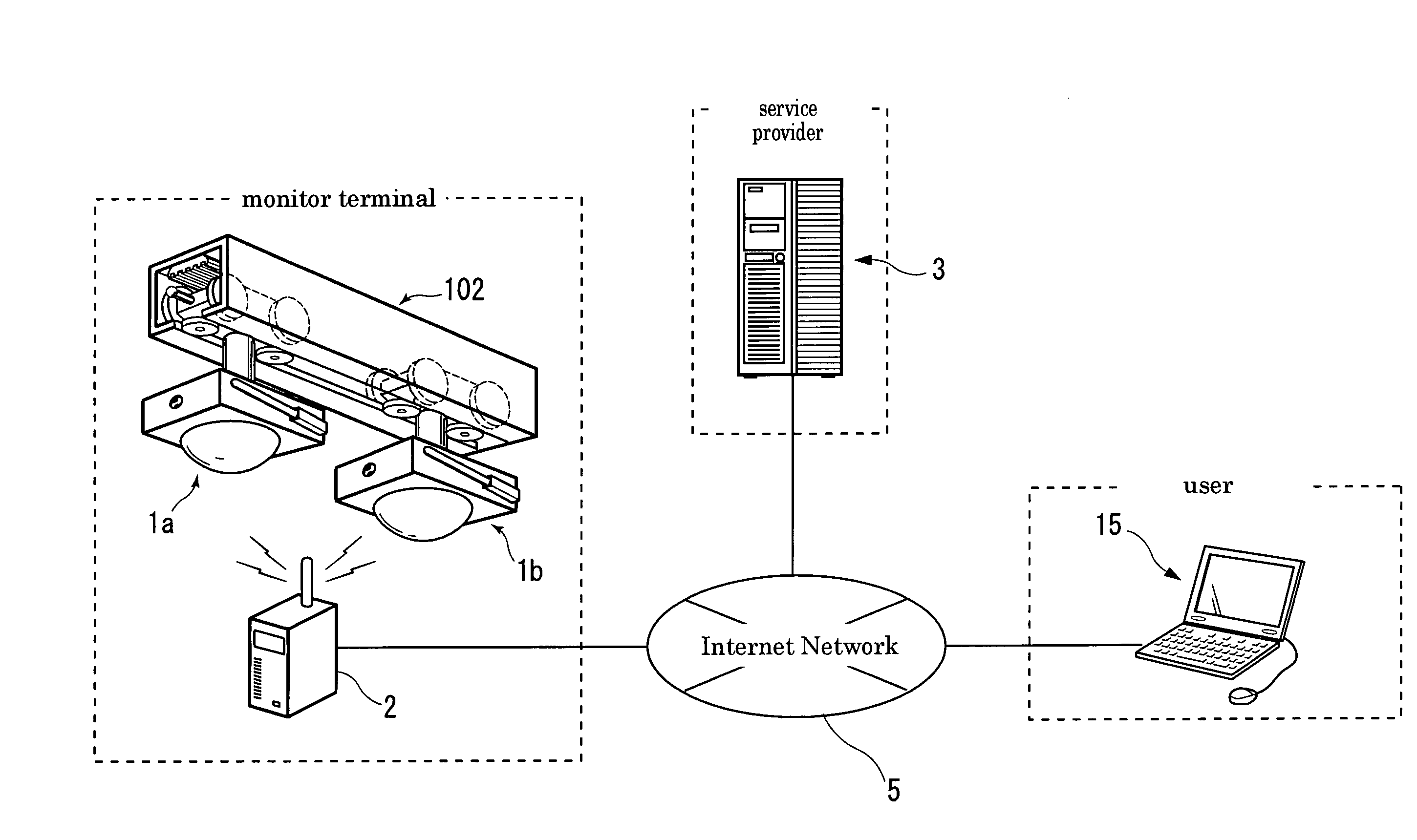
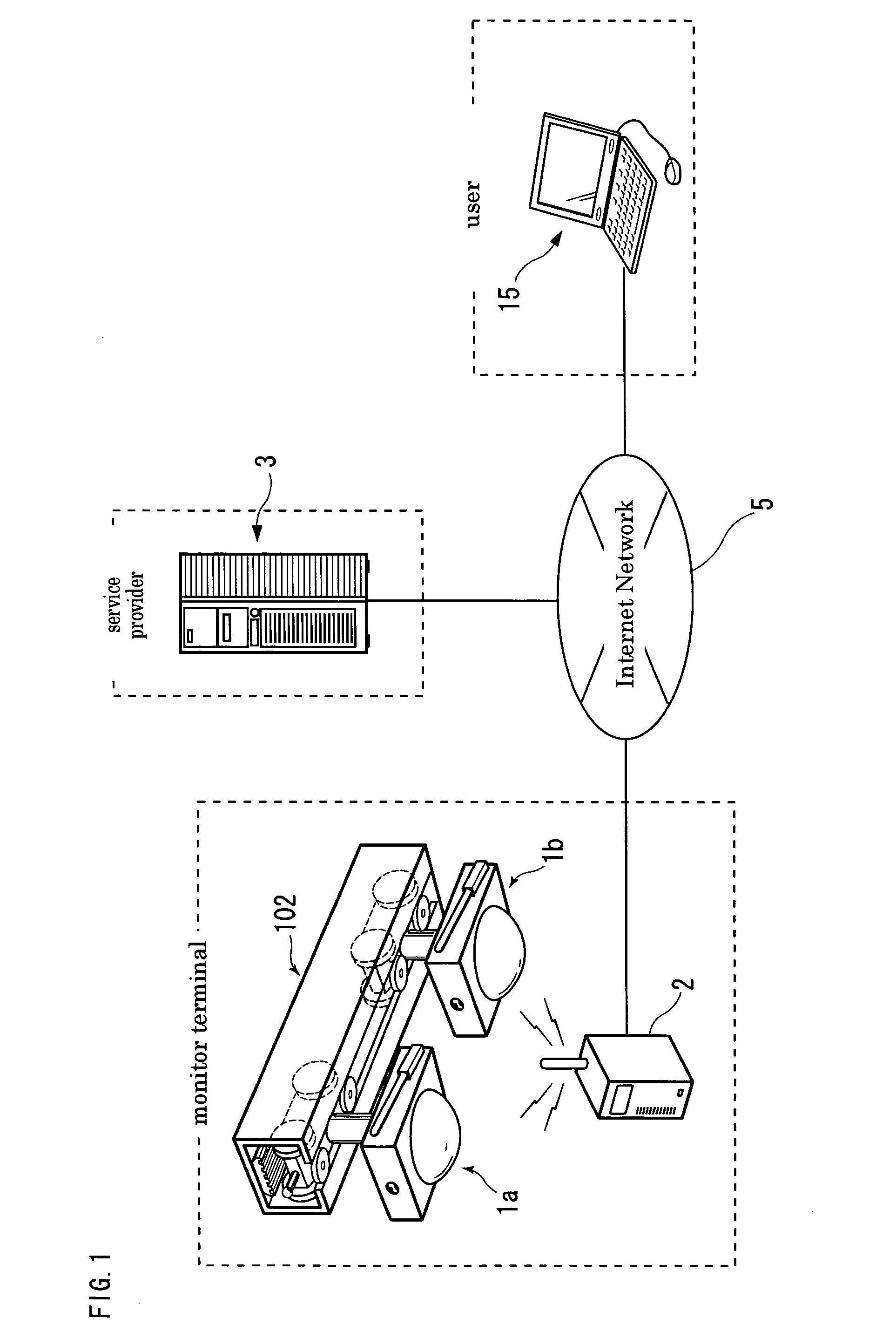
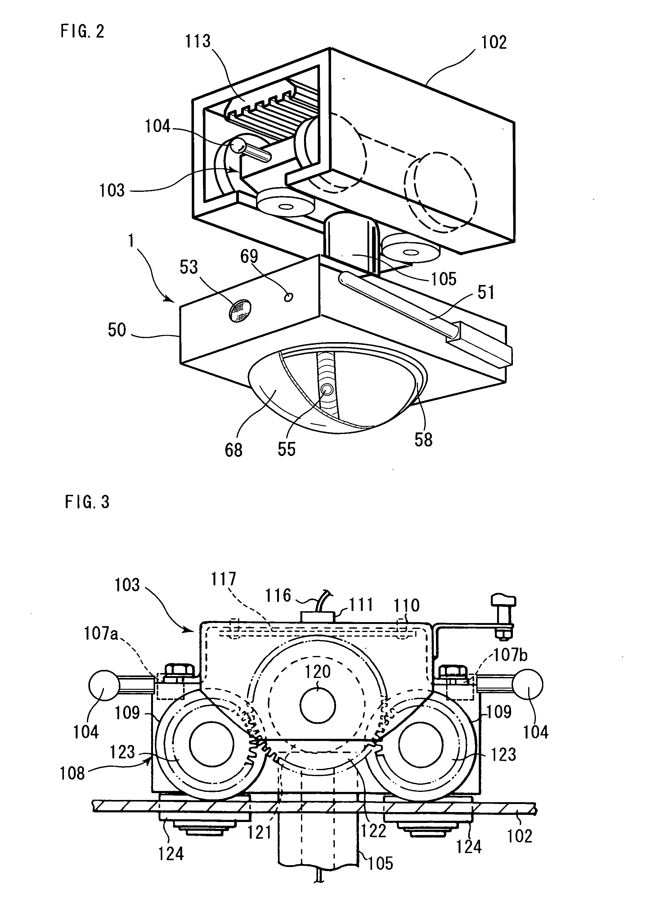
[0031] Firstly, FIG. 1 is the block diagram showing the constitution of the monitoring system of a specific area of this embodiment, FIG. 2 is the external perspective view showing the moving unit that constitutes the monitor terminal used in the monitoring system of a specific area of this embodiment, FIG. 3 is the side view showing the moving cart that is connected to the moving unit used in this embodiment, FIG. 4 is the sectional view showing the moving rail and the moving cart, which are the moving means used in this embodiment, FIG. 5 is the block diagram showing the constitution of the moving unit that constitutes the monitor terminal used in this embodiment, FIG. 6 is the block diagram showing the constitution of the fixed unit 2 that constitutes the monitor terminal used in this embodiment, FIG. 7 is the block diagram showing the constitution of the access module used in this embodiment, FIG. 8 is the block diagram showing the constitution of the administrative computer use...


PUM


Abstract

A monitoring system of a specific area comprising monitor terminals each having an image pickup unit and disposed to move on a moving means in an area being monitored, and a monitor which can display at least a monitor image picked up by the image pickup unit. The monitoring system of a specific area further comprises a monitor image switching means for receiving monitor images from the monitor terminals and transmitting the monitor images to the monitor, and a proximity detecting means provided in the monitor terminal for detecting other monitor terminal existing in close proximity on the same or adjacent moving path. When the proximity detecting means detects other monitor terminal, the monitor terminal transmits detection information of other monitor terminal to the monitor image switching means which switches the image being transmitted to the monitor to the monitor image of other monitor terminal based on the received detection information thereof.

Description

FIELD OF THE INVENTION [0001] The present invention relates to a monitoring system of a specific area, which is capable of performing remote monitoring of a specific area where monitor terminals are disposed, by using a monitoring system such as a telephone and a personal computer that a user has. BACKGROUND ART [0002] Due to the deterioration of a security level in recent years, monitoring systems of a specific area have been proposed, by which a user can monitor the condition of the specific area such as the inside of home by using a communication line (including wire and wireless) when necessary or even intermittently frequently not limited to an occasion when the user becomes worried. [0003] However, in these monitoring systems, in order to perform remote monitoring of the specific area to be monitored by monitor images picked up by a monitor terminal having an image pickup unit such as a monitor camera, only a part of the specific area to be monitored can be monitored if only o...

Claims


Application Information

Patent Timeline
Patent Type & Authority Applications(United States)
IPC IPC(8): G08B13/196H04N7/18
CPCG08B13/19623G08B13/19641G08B13/19656G08B13/19667H04N5/76H04N7/17318H04N21/6587H04N7/185H04N21/41407H04N21/4143H04N21/4223H04N21/47202H04N21/6581H04N7/181
Inventor NOGUCHI, NAOHEI
Owner DENARO
Why Eureka
Try Eureka