Image encoding apparatus, and image processing apparatus and its control method

a technology of image data and encoding apparatus, applied in the field of encoding technique of image data, can solve the problems of inability to be processed by general applications, inability to reflect high precision of image data in compression-encoding data, and inability to generate target encoded data, etc., to suppress the drop in arithmetic precision.

Inactive Publication Date: 2005-12-15
CANON KK
View PDF6 Cites 37 Cited by
  • Summary
  • Abstract
  • Description
  • Claims
  • Application Information

AI Technical Summary

Benefits of technology

[0020] The present invention has been made in consideration of the aforementioned problems, and has as its object to provide a technique for generating target encoded data by suppressing an arithmetic precision drop by executing processes such as orthogonal transformation and the like using the number of bits of an input image in place of reducing the number of bits at the time of input upon encoding an image. It is another object of the present invention to provide a technique which generates a high-precision, high-quality decoded image while compression-encoding image data to be transferred from an image input device to an image output device.

Problems solved by technology

However, when data exceeding 12 bits are encoded like JPEG, such encoded data becomes non-standard data, and cannot be processed by general applications.
Under such circumstances, it is no use increasing the number of output bits by higher performance of an image input device, and high precision of image data cannot be reflected in the compression-encoded data.
However, the multi-bit input function of the image input device is not effectively used, and it becomes useless in practice.

Method used


Image

  • Image encoding apparatus, and image processing apparatus and its control method
  • Image encoding apparatus, and image processing apparatus and its control method
  • Image encoding apparatus, and image processing apparatus and its control method

Examples


first embodiment

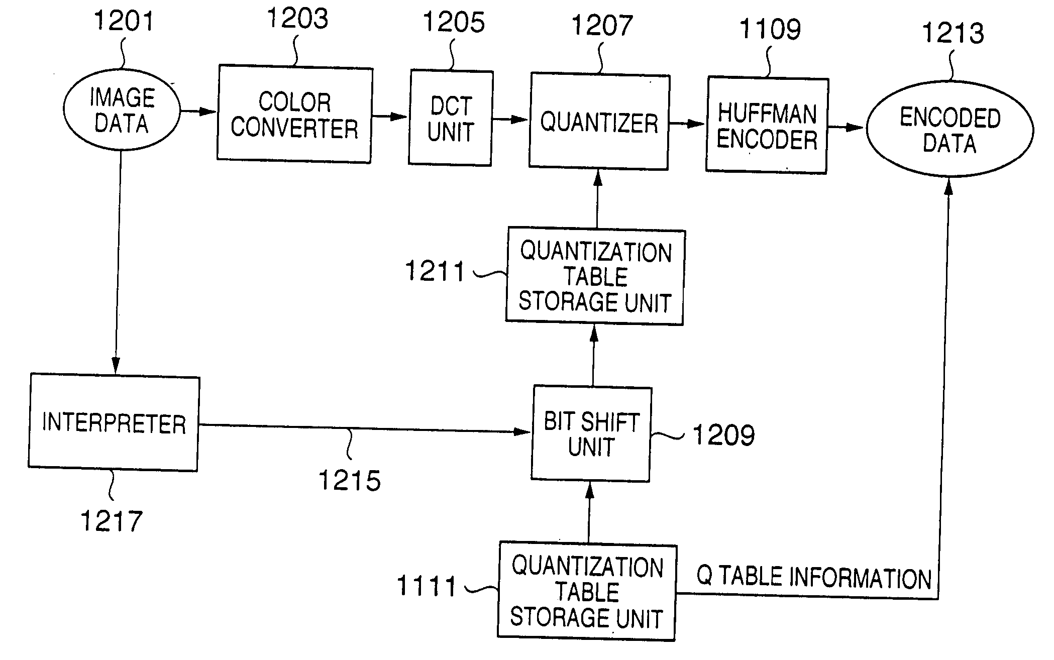
[0043] This embodiment will exemplify an encoding apparatus for generating encoded data from 16-bit image data per component, which obtains baseline JPEG encoded data (each color component of a decoded image is 8 bits), and Extended sequential DCT-based JPEG encoded data each color component of a decoded image is 12 bits).

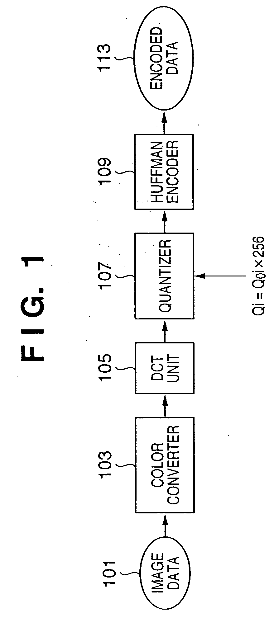
[0044]FIG. 11 is a block diagram of an encoding apparatus of this embodiment. The difference from FIG. 10 is that processors except for the Huffman encoder 1109 and quantization table storage unit 1111 in FIG. 10 have processing performance that supports a 16-bit full range input. More specifically, the number of bits to be processed is extended by 8 bits in the MSB direction.

[0045] In order to distinguish the processors except for the above two processors from the conventional 8-bit compatible processors, different numbers are given as follows.

[0046] Reference numeral 1201 denotes input 16-bit full-color image data per color; 1203, 1205, and 1207, a 16-bit data...

implementation example

Description of Implementation Example

[0065]FIG. 13 is a block diagram when the image encoding apparatus of this embodiment is applied to a digital camera apparatus (image sensing apparatus).

[0066] Referring to FIG. 13, reference numeral 1001 denotes a CPU which controls the overall apparatus; 1002, a ROM which stores the processing sequence of the CPU 1001; and 1003, a RAM used as a work area. This RAM 1003 is used to temporarily store sensed image data so as to encode it. Also, areas serving as a first quantization table storage unit corresponding to the quantization table storage unit 1211 shown in FIG. 11, and a second quantization storage unit corresponding to the quantization table storage unit 1111 are assured on this RAM 1003.

[0067] Reference numeral 1004 denotes a connector used to connect a detachable memory card (storage medium) 1005. Reference numeral 1006 denotes an optical unit which comprises a lens, stop, and the like; and 1007, an optical unit controller for contro...

second embodiment

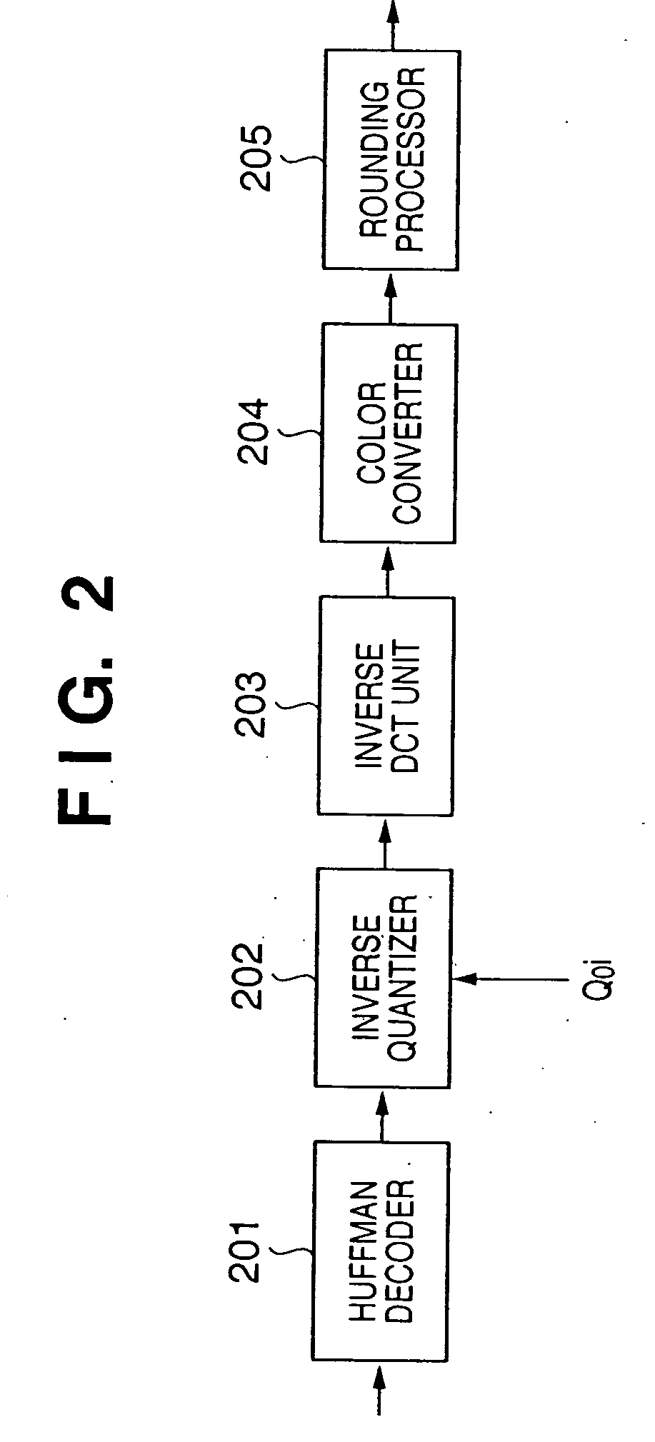
[0109] The second embodiment will explain a case wherein image data which is expressed by 16 bits per color component undergoes a JPEG encoding process to obtain an encoded bitstream, and that encoded bitstream is decoded to output an image which is expressed by 8 bits per color component.

[0110]FIG. 5 is a block diagram of an image processing apparatus (copying machine) to which the second embodiment is applied.

[0111] Referring to FIG. 5, reference numeral 501 denotes a scan unit which scans a document image with a precision of 16 bits per color component; 502, an encoding unit; 503, a decoding unit; and 504, a print unit which receives and prints an image which is expressed by 8 bits per color component. Reference numeral 505 denotes a storage device which stores encoded data output from the encoding unit 502. The decoding unit 503 reads out encoded data from the storage device 505 in accordance with the print speed of the print unit 504, and performs a decoding process. As a res...


PUM


Abstract

This invention generates target encoded data by suppressing an arithmetic precision drop by executing processes such as orthogonal transformation and the like using the number of bits of an input image in place of reducing the number of bits at the time of input upon encoding an image. Upon generating baseline JPEG encoded data, a quantization table for an 8-bit image is stored in a quantization table storage unit. When an interpreter outputs information indicating that each color component per pixel of input image data is 16 bits, a bit shift unit multiplies the quantization table stored in the quantization table storage unit by the 8th power of 2 or {8th power of 2+1}. A quantizer quantizes coefficients output from a DCT unit on the basis of the quantization table stored in the quantization table storage unit, and a Huffman encoder encodes the quantization result to Huffman codes. A header is created by setting information indicating baseline JPEG and the quantization table stored in the quantization table storage unit, thus generating encoded data.

Description

FIELD OF THE INVENTION [0001] The present invention relates to an encoding technique of image data. BACKGROUND OF THE INVENTION [0002] In JPEG as an international standard encoding scheme of still image data, encoding / decoding processes of color image data of 8 bits per component and color image data of 12 bits per component are specified as a lossy encoding scheme using discrete cosine transformation (DCT). Encoding of an 8-bit image is classified as a Baseline process, and that of a 12-bit image, including 8-bit image, is classified as an Extended DCT-based process. This is specified in a reference “ITU-T recommendation T.81 (ISO / IEC 10918-1)”. [0003] Table B.2 in Section B.2.2. of Annex B of this reference specifies the sizes and values of frame header parameters. Also, the numbers of bits to be encoded / decoded are specified as the second parameter P. Baseline sequential DCT, i.e. the Baseline process is limited to an 8-bit image, and the Extended DCT-based process including Exte...

Claims


Application Information

Patent Timeline
Patent Type & Authority Applications(United States)
IPC IPC(8): G06K9/36H04N7/26H04N7/30
CPCH04N19/126H04N19/60
Inventor NAKAYAMA, TADAYOSHIKISHI, HIROKI
Owner CANON KK
Why Eureka
Try Eureka