Apparatus and method for control of solid desiccant dehumidifiers

a desiccant dehumidifier and desiccant technology, applied in lighting and heating apparatus, heating types, separation processes, etc., can solve the problems of insufficient dehumidification space or process, complex system, limited dehumidification system, etc., and achieve maximum flexibility in operation.

Active Publication Date: 2017-10-03
BRY AIR ASIA PVT
View PDF23 Cites 1 Cited by
  • Summary
  • Abstract
  • Description
  • Claims
  • Application Information

AI Technical Summary

Benefits of technology

[0019]It is an important object of the present invention is to provide a method and a system for control of solid desiccant dehumidifiers that ensures maximum flexibility in operation.
[0021]It is a further object of the invention to provide a solid desiccant based dehumidification system that has a significantly high level of flexibility in operational control, wherein the parameters requiring control are capable of being chosen by the user.
[0023]It is a further object of the invention to provide an apparatus and method that require minimal expense and are yet flexible in operation thereby providing better data generation for monitoring of reactivation in a desiccant wheel.SUMMARY OF THE INVENTION
[0050]It is significantly easier, less expensive and more reliable to measure air temperature than air humidity. Simple and inexpensive temperature measuring devices such as thermocouples and thermistors may be used. One of the unique features of the present invention is the measurement of the air temperatures entering and leaving a desiccant wheel to infer the dehumidification or reactivation that is occurring at any given angular position in the wheel during its rotation.

Problems solved by technology

Refrigeration based dehumidification systems are limited in the moisture they can remove.
This is because, below a certain dew point humidity, freezing of the coiling coil occurs, thereby requiring a defrost cycle that makes the system more complex.
When the air is dried to the required humidity, it is often too cold for the dehumidified space or process.
Desiccant dehumidifiers use a considerable amount of heat energy to regenerate or reactivate the desiccant.
The method used to determine either temperature or moisture content of the supply gas are therefore, necessarily limited to those that can be used with closed loop steam supply systems.
This does not provide flexibility in the system operation.
The method herein does not provide the necessary flexibility of operation that is desirable and does not enable dynamic control.
Again, the method herein does not provide the necessary flexibility of operation that is desirable and does not enable dynamic control due to its almost exclusive reliance on measuring average air temperature rise through the process sector to ensure that this is kept at a predetermined value.
The patent is specific to systems with two dehumidifiers in series, and lacks the necessary flexibility that is desirable for solid desiccant based dehumidification systems.
Again, the disclosure of this document does not provide any solution to achieving flexibility of operational control in a dynamic manner in solid desiccant based dehumidification systems.

Method used


Image

  • Apparatus and method for control of solid desiccant dehumidifiers
  • Apparatus and method for control of solid desiccant dehumidifiers
  • Apparatus and method for control of solid desiccant dehumidifiers

Examples


Embodiment Construction

[0051]The following comprises a non-limiting description of the accompanying drawings that accompany this specification.

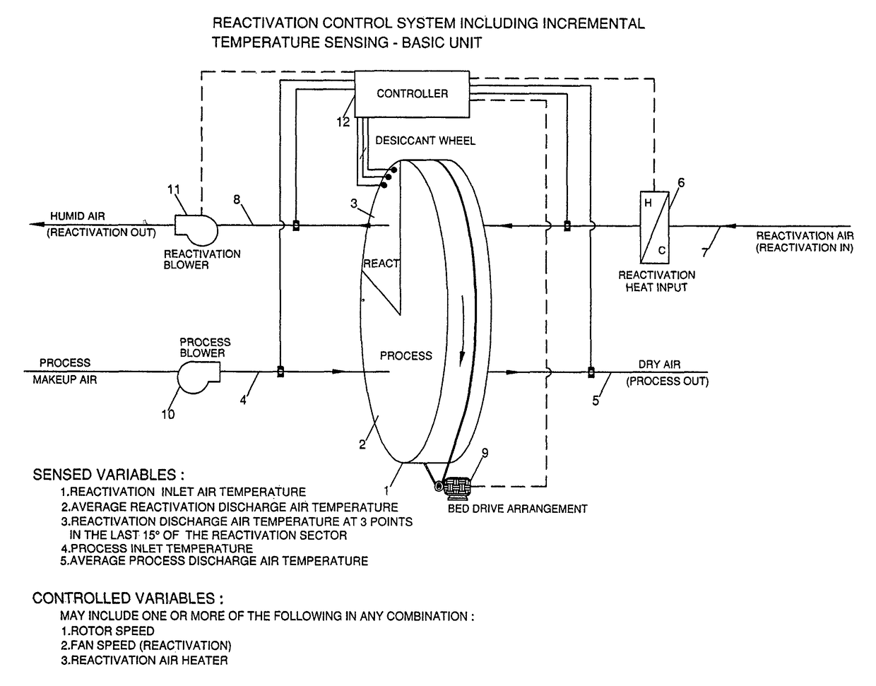
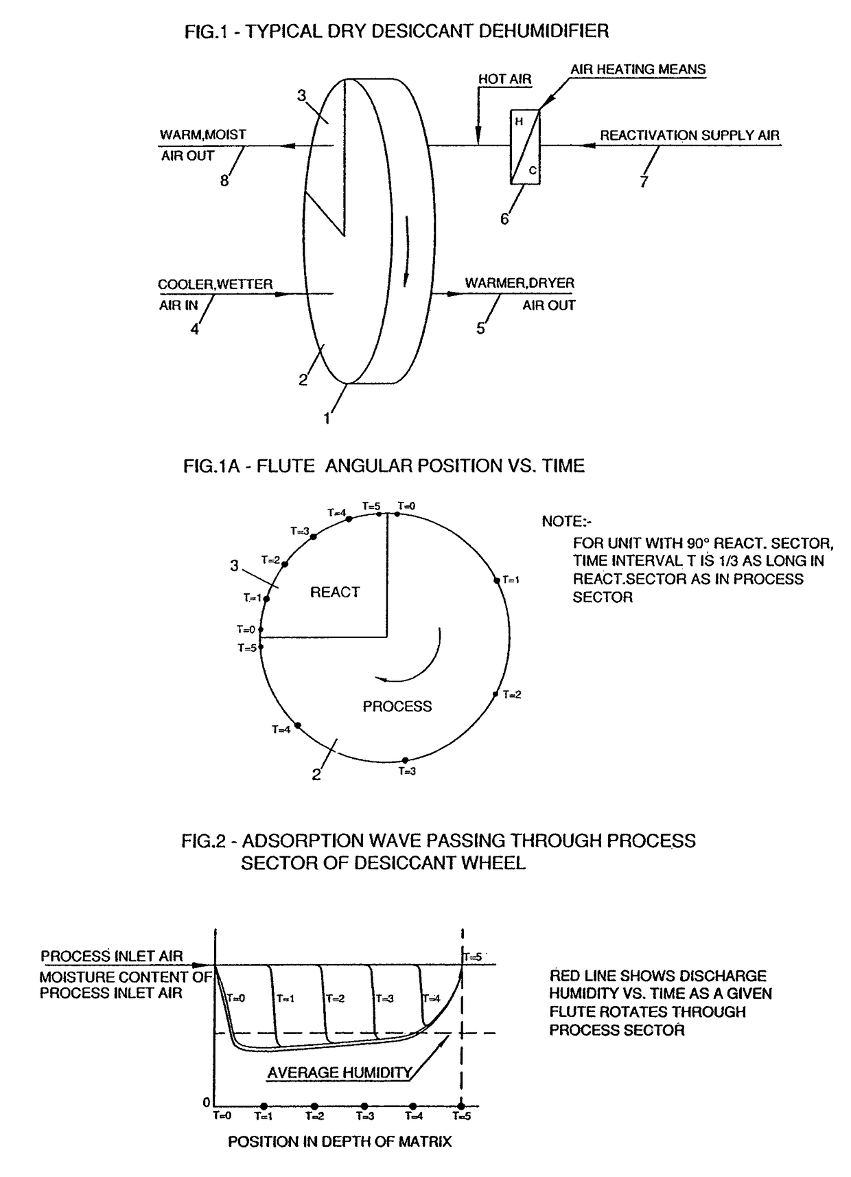
[0052]FIG. 1 is a schematic of a basic solid desiccant dehumidifier. The arrangement and operational characteristics of this type of dehumidifier are well-known in the art.

[0053]FIG. 1A shows the angular position of any given point in the wheel 1 as a function of time, as it passes through the process 2 and reactivation 3 sectors. The time periods shown in the reactivation sector 3 are shorter than those shown in the process sector 2, in direct proportion to the relative sizes of the process 2 and reactivation 3 sectors.

[0054]FIG. 2 schematically shows the relationship of process air 5 discharge humidity vs. the time spent in the process sector 2 of any given angular location within the wheel 1 as it rotates through the process sector 2. The effect of the adsorption wave on discharge air 5 humidity can be seen.

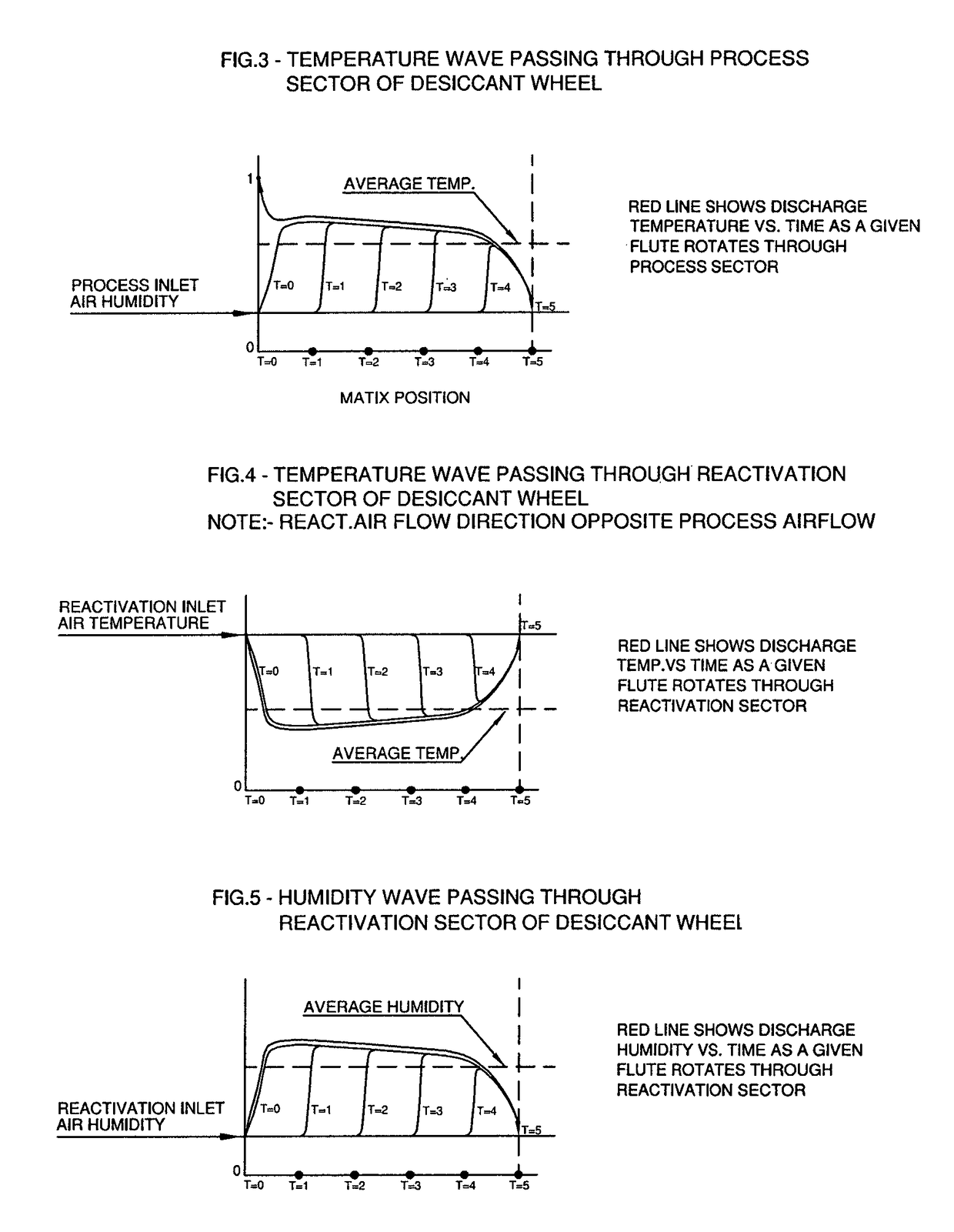
[0055]FIG. 3 schematically shows the relationship of pr...


PUM


Abstract

The present invention generally discloses desiccant dehumidifiers control systems. In particular, the present invention relates to solid desiccant dehumidifiers which use a rotor (commonly called a wheel) to dehumidify a process airstream. The invention provides a novel apparatus for control of desiccant dehumidifiers and to an improved method of control of such dehumidifiers, and also to dehumidifiers provided with such control systems.

Description

RELATED APPLICATIONS[0001]This application is a U.S. national phase application under 35 USC §371 of PCT / IN2012 / 000609 filed on Sep. 12, 2012, and claims the benefit under 35 USC §119 of Indian patent application number 2629 / DEL / 2011 filed September 12, the disclosures of which are incorporated herein by reference in their entireties.FIELD OF THE INVENTION[0002]The present invention relates generally to desiccant dehumidifiers control systems. In particular, the present invention relates to solid desiccant dehumidifiers which use a rotor (commonly called a wheel) to dehumidify a process airstream. The invention provides a novel apparatus for control of desiccant dehumidifiers and to an improved method of control of such dehumidifiers, and also to dehumidifiers provided with such control systems.BACKGROUND OF THE INVENTION[0003]Dehumidification is a process of removing moisture from air. There are several known methods of dehumidifying air. However, the two most common methods use re...

Claims


Application Information

Patent Timeline
Patent Type & Authority Patents(United States)
IPC IPC(8): B01D53/02F24F11/00B01D53/26F24F3/14
CPCF24F3/1423B01D53/261F24F3/1429F24F11/00F24F11/0012F24F11/0076F24F2003/144F24F2003/1458F24F2203/10F24F11/30F24F2110/10F24F11/70F24F11/77F24F11/46F24F11/63F24F2140/00
Inventor PAHWA, DEEPAKGRIFFITHS, WILLIAM CHARLESSACHDEV, RAJANMALIK, KULDEEP SINGH
Owner BRY AIR ASIA PVT
Why Eureka
Try Eureka