Electrical connector with improved crosstalk compensation

a technology of crosstalk compensation and electrical connector, which is applied in the direction of coupling device connection, coupling protection earth/shielding arrangement, and contact member of securing/insulating coupling, etc., can solve the problems of increasing problems such as crosstalk due to capacitive and inductive couplings among closely spaced parallel conductors within the jack and/or plug

Active Publication Date: 2005-12-15
PANDUIT
View PDF59 Cites 56 Cited by
  • Summary
  • Abstract
  • Description
  • Claims
  • Application Information

AI Technical Summary

Problems solved by technology

In the communications industry, as data transmission rates have steadily increased, crosstalk due to capacitive and induct

Method used


Image

  • Electrical connector with improved crosstalk compensation
  • Electrical connector with improved crosstalk compensation
  • Electrical connector with improved crosstalk compensation

Examples


Embodiment Construction

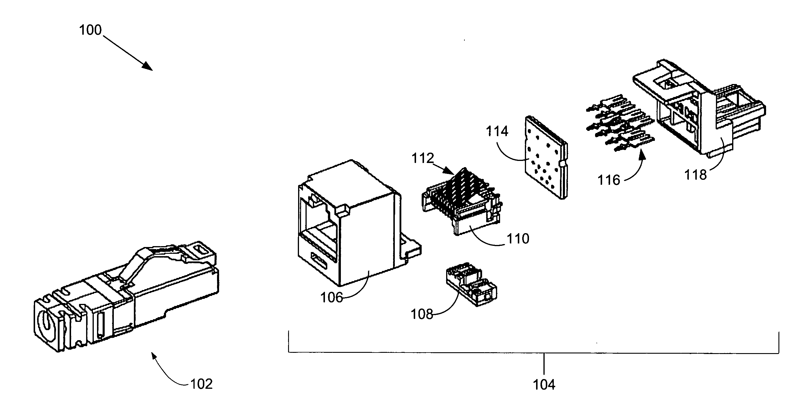
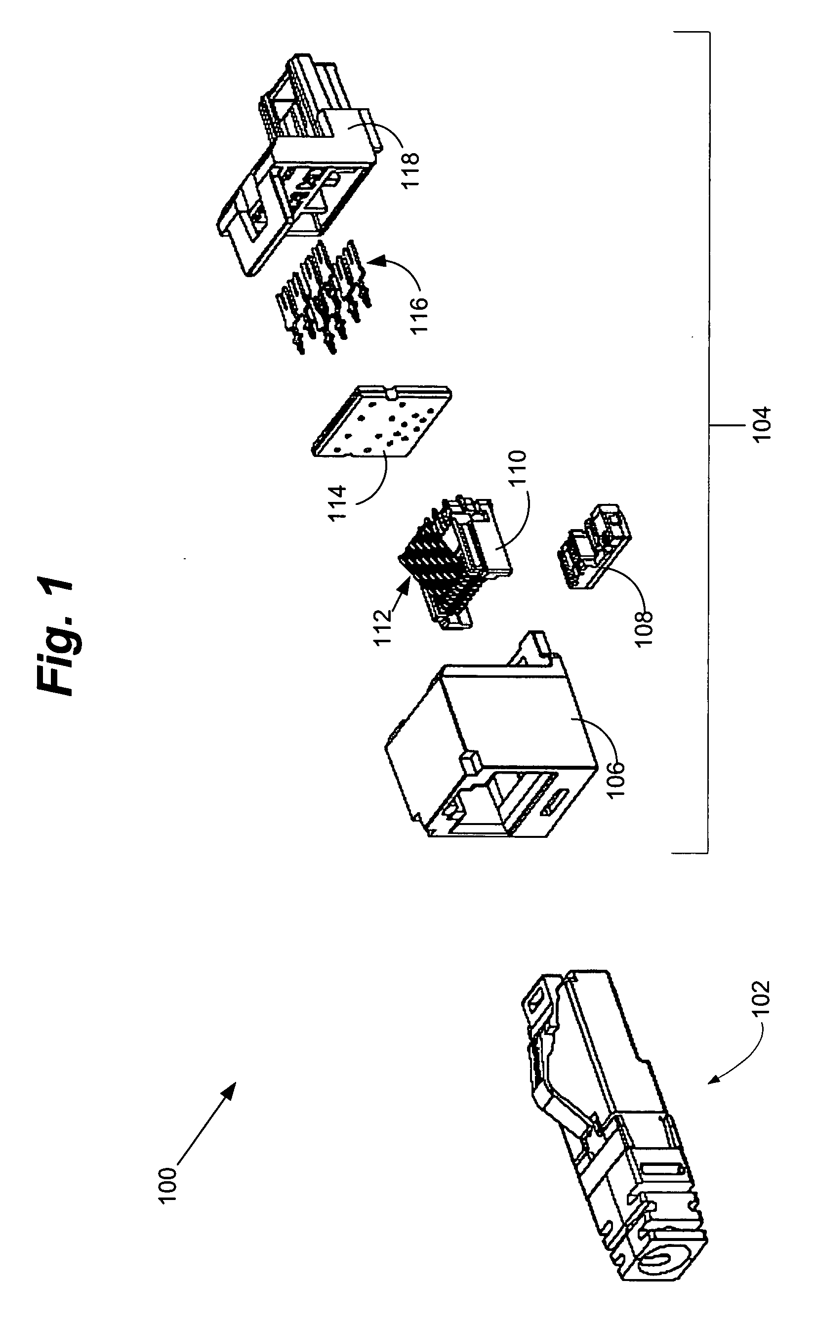
[0049]FIG. 1 is an exploded perspective illustration of a communication connector 100 comprising a plug 102 and a jack 104, into which the plug 102 may be inserted. The plug 102 terminates a length of twisted pair communication cable (not shown), while the jack 104 may be connected to another piece of twisted pair communication cable or punch-down block (neither of which is shown in FIG. 1)

[0050] As shown from left to right, the jack 104 includes a main housing 106 and a bottom front sled 108 and top front sled 110 arranged to support eight plug interface contacts 112. The plug interface contacts 112 engage a PCB (Printed Circuit Board) 114 from the front via through-holes in the PCB 114. As illustrated, eight IDCs (Insulation Displacement Contacts) 116 engage the PCB 114 from the rear via additional through-holes in the PCB 114. A rear housing 118 having passageways for the IDCs 116 serves to provide an interface to a twisted pair communication cable or punch-down block. The gener...


PUM


Abstract

An electrical connector with improved crosstalk compensation is disclosed. By including at least one coupling with a different frequency dependency than other couplings in the connector, crosstalk compensation performance is improved over a greater frequency range. The different frequency dependency may, for example, be used to compensate for phase shifts caused by distances between compensation circuitry and the plug/jack interface. Embodiments for decreasing these distances are also disclosed.

Description

CROSS-REFERENCE TO RELATED APPLICATION [0001] This application claims priority to U.S. Provisional Application Ser. No. 60 / 559,846, filed on Apr. 6, 2004, the entirety of which is hereby incorporated by reference.FIELD OF THE INVENTION [0002] The present invention relates generally to electrical connectors, and more particularly, to a modular communication jack design with crosstalk compensation that is less susceptible to propagation delay effects at high frequencies. BACKGROUND OF THE INVENTION [0003] In the communications industry, as data transmission rates have steadily increased, crosstalk due to capacitive and inductive couplings among the closely spaced parallel conductors within the jack and / or plug has become increasingly problematic. Modular connectors with improved crosstalk performance have been designed to meet the increasingly demanding standards. Many of these improved connectors have included concepts disclosed in U.S. Pat. No. 5,997,358, the entirety of which is in...

Claims


Application Information

Patent Timeline
IPC IPC(8): H01R13/40H01R13/6464H01R13/6474H01R13/658H01R13/719H01R24/58H05K1/02
CPCH05K1/0228H01R13/6464H01R13/6466H01R13/719H01R24/64Y10S439/941
Inventor CAVENEY, JACK E.BOLOURI-SARANSAR, MASUD
Owner PANDUIT
Why Eureka
Try Eureka