Storage control system and operating method for storage control system

Inactive Publication Date: 2005-12-15
HITACHI LTD
View PDF18 Cites 30 Cited by
  • Summary
  • Abstract
  • Description
  • Claims
  • Application Information

AI Technical Summary

Benefits of technology

[0006] Accordingly, it is an object of the present invention to improve the reliability of storage control syst

Problems solved by technology

In the conventional storage control system above, when a fault arises with a certain disk connector, there are sometimes cases where access is then no longer possible not

Method used


Image

  • Storage control system and operating method for storage control system
  • Storage control system and operating method for storage control system
  • Storage control system and operating method for storage control system

Examples


embodiment example 1

[0090]FIG. 14 shows parts relating to the data transfer of the storage control system 120 relating to a first embodiment example of an embodiment of the present invention.

[0091] A first alternate path 510 is provided between the CTL 5B and PBC 101A. Further, a second alternate path 512 is provided between the CTL 5A and PBC 101B. In this case, when it is detected that a fault has occurred with the disk connector 111A, for example, the CTL 5A is able to access each disk connector 111B under the management of CTL 5B directly via the second alternate path 512.

embodiment example 2

[0092]FIG. 15 shows an example of a fiber channel loop connection for a controller unit and disk enclosures.

[0093] In the second embodiment example, the leading disk enclosure 117 among the plurality of serially connected disk enclosures 117 is connected to one controller unit 5. Two FC loops 180A and 180B exist in each disk enclosure 117 and a plurality of HDD 115 is connected to the FC loops 180A and 180B respectively (the illustrated example is an example in which one HDD 115 can be accessed by two FC loops 180A and 180B). A first large loop is formed by a plurality of serially connected FC loops 180A and a second large loop is formed by a plurality of serially connected FC loops 180B.

[0094] Each disk enclosure 117 comprises a first fiber channel switch (FC-SW hereinbelow) 401 that disconnects the FC loop 180A from the first large loop and passes the first large loop to the next disk enclosure 117, and a second FC-SW 403 that disconnects the FC loop 180B from the second large l...


PUM


Abstract

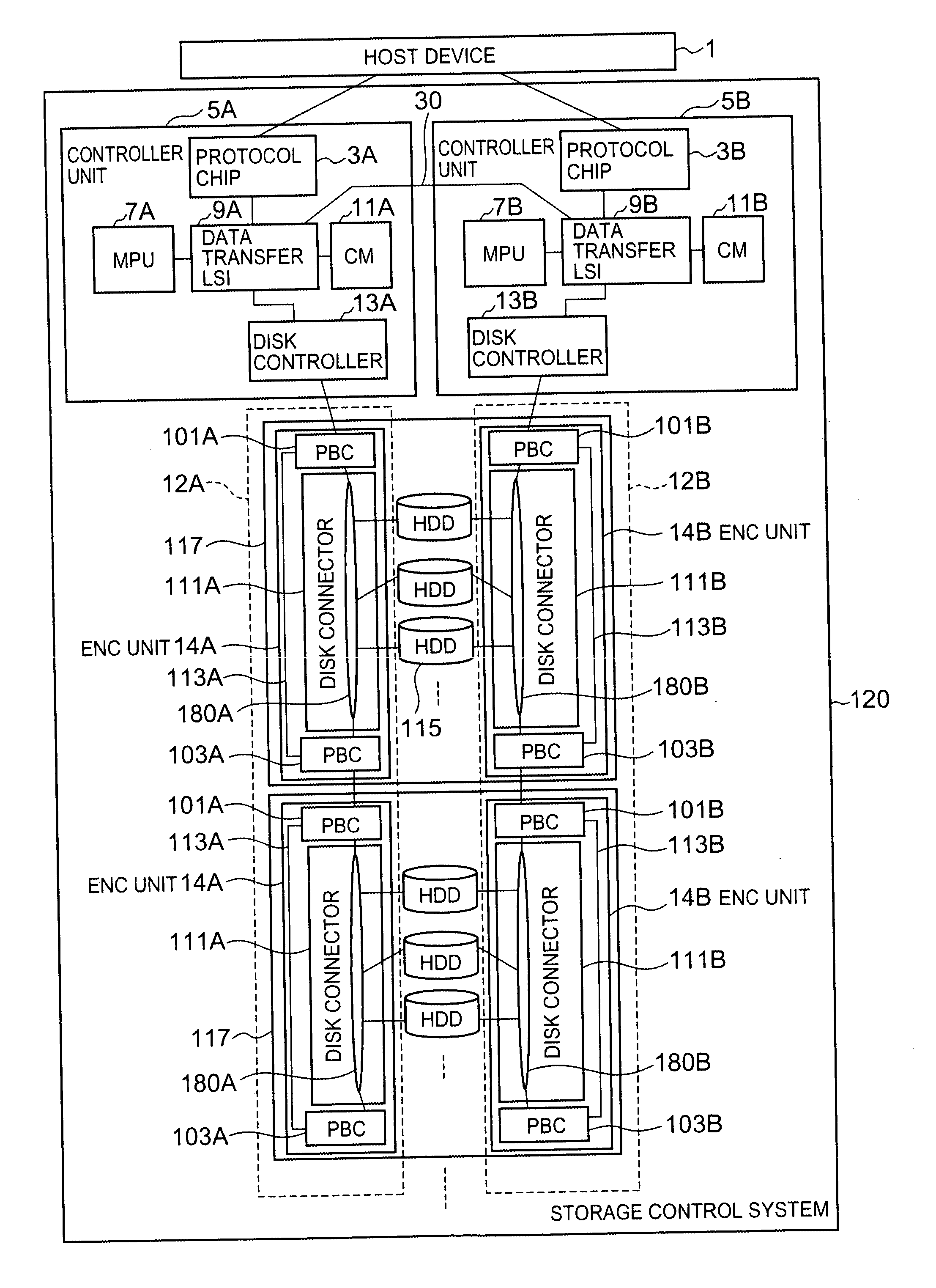
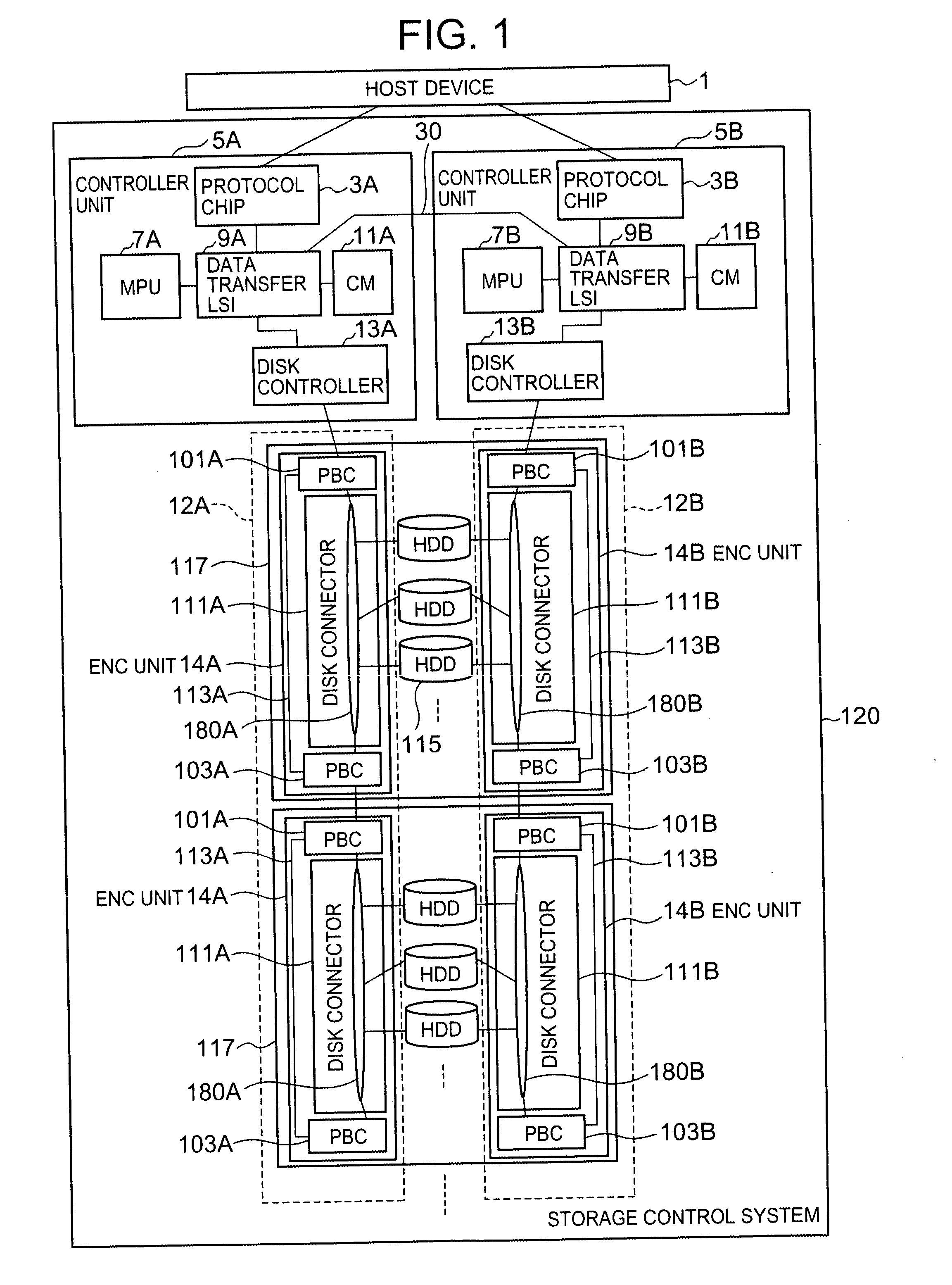
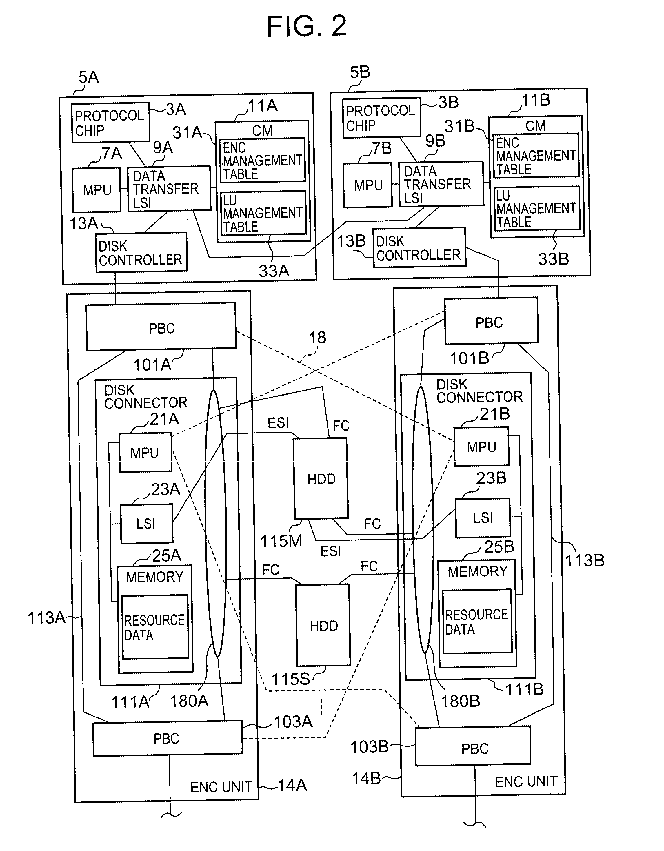
Each disk enclosure 117 contains an ENC bypass 113A for a disk connector 111A, and PBC 101A and 103A, which perform selective switching to transfer data via either the disk connector 111A or the ENC bypass 113A. When the occurrence of an anomaly in the disk connector 111A is detected, the CTL 5A connected to the disk connector 111A asks the CTL 5B to bypass the disk connector 111A, whereupon the CTL 5B switches the data communication path from the disk connector 111A to the ENC bypass 113A by controlling the PBC 101A and 103A.

Description

CROSS-REFERENCE TO PRIOR APPLICATION [0001] This application relates to and claims priority from Japanese Patent Application No. 2004-157365, filed on May 27, 2004, the entire disclosure of which is incorporated herein by reference. FIELD OF THE INVENTION [0002] The present invention relates to a storage control system comprising a plurality of storage devices, and to an operating method for the storage control system. BACKGROUND OF THE INVENTION [0003] The storage control systems disclosed in Japanese Patent Applications Laid Open Nos. 2004-22058 and 2004-22059, for example, are known as storage control systems that comprise a plurality of disk drives. [0004] Such storage control systems comprise a basic disk chassis and one or more additional disk chassis. The basic disk chassis comprises a controller, a plurality of disk drives, and a disk connector (port bypass circuit, for example) that connects the controller and the plurality of disk drives. The additional disk chassis are co...

Claims


Application Information

Patent Timeline
IPC IPC(8): G06F11/00G06F3/06G06F11/20
CPCG06F11/2007G06F11/2089G06F11/201
Inventor JIANG, XIAOMINGSUZUKI, KATSUYOSHI
Owner HITACHI LTD
Why Eureka
Try Eureka