Hydroentangling process

a technology of water entanglement and process, applied in the field of water entanglement process, can solve the problems of reduced process efficiency of cellulosic pulp, short fibers that remain, dust from the formed product, etc., and achieves the effect of less fiber loss, efficient process and more efficient process

Inactive Publication Date: 2005-12-22
WESTLAND JOHN A +1
View PDF19 Cites 21 Cited by
  • Summary
  • Abstract
  • Description
  • Claims
  • Application Information

AI Technical Summary

Benefits of technology

[0012] This use of this long fiber fraction has a number of benefits when compared to using the entire pulp material. The energy needed to fiberize a pulp sheet or bale having only a long fiber fraction is less than the energy required to fiberize a pulp sheet or bale of the prefractionated pulp. There is less loss of fiber in the hydroentangling process when only the long fiber fraction is used giving a more efficient process. The process is also more efficient because with the reduced amount of fines and short fibers being recycled through the process there is less time needed to clean and maintain filters. The airlaced product is improved due to greater adhesion between the long fibers and the non-woven web.

Problems solved by technology

Cellulosic pulp fibers may be used in the formation of spunlaced or airlaced mats A problem is that the fines or short fibers normally found in cellulosic pulp reduce the efficiency of the process.
Another problem is that the fines and short fibers that remain in the mat do not become attached to the non-woven web and may dust from the formed product.

Method used


Image

  • Hydroentangling process
  • Hydroentangling process

Examples


Embodiment Construction

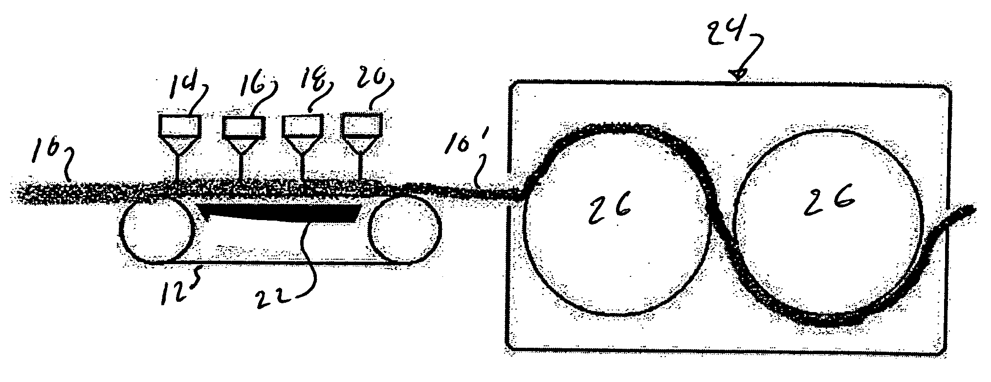
[0015]FIG. 1 shows an apparatus for spunlacing a mat of fibers. The mat 10 is carried onto a conveyor 12 and passes under a series of water jets 14, 16, 18 and 20. The water jets are usually at increasing water pressure. There is a vacuum chamber 22 underneath the conveyor 12. The water from the jets 14, 16, 18 and 20 pass through the mat 10 entangling the fibers. The water is pulled from the mat by the vacuum in chamber 22. The mat of entangled fibers 10′ is transported into the dryer section 24 and dried. Dryer cans 26 are shown. The mat is then rolled up or boxed for shipment.

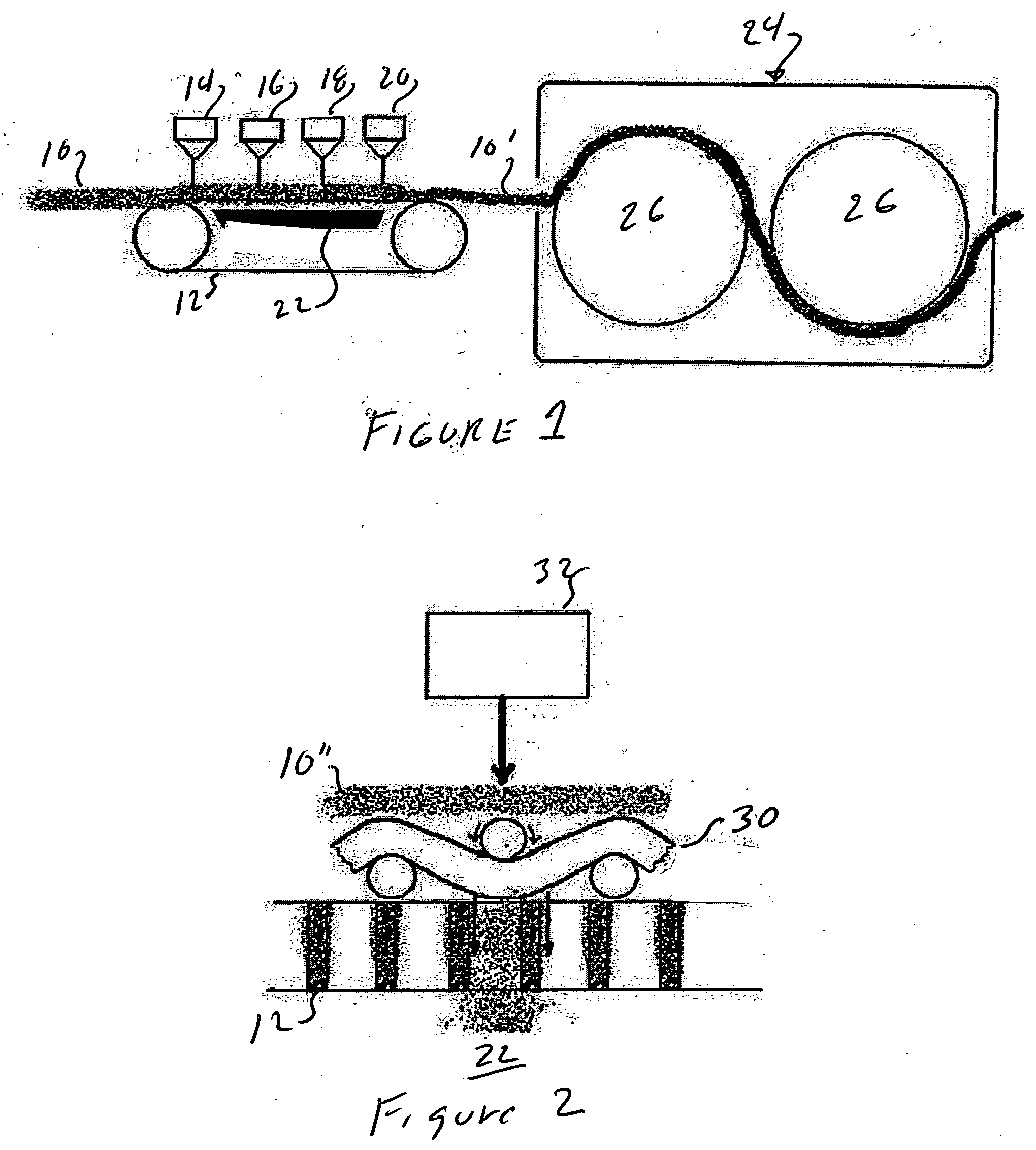
[0016]FIG. 2 shows airlacing. The apparatus would be the same as the apparatus in FIG. 1. The difference between FIGS. 1 and 2 is the web 30. The water jet 32, which is one of a series of water jets, displaces the fibers in the mat 10″ downwardly and entangles the fibers with the web 30. The composite web is then dried as shown in FIG. 1.

[0017] The pulp fibers that may be used are mechanical pulp fibers, t...


PUM

PropertyMeasurementUnit
length weighted average lengthaaaaaaaaaa
lengthaaaaaaaaaa
lengthaaaaaaaaaa

Abstract

A hydroentangling process comprising providing fractionated cellulosic fibers having a length weighted average length of at least 2.4 mm and less than 2% on a weight basis of fines having a length no greater than 0.2 mm, forming said fibers into a mat, applying jets of fluid under pressure to the pulp fibers to entangle said fractionated cellulosic fibers. The fibers may be entangled with a nonwoven web.

Description

BACKGROUND OF THE INVENTION [0001] The oldest technique for consolidating a web is mechanical bonding. The fibers are entangled to give strength to the web. One method of entangling the fibers is spunlacing. Spunlacing is also known as hydroentanglement, jet entanglement, water entangled, hydraulically needled or hydraulically loomed. In spunlacing high pressure jets of water strike a web so that the fibers in the web become entangled and form a nonwoven web. The jets are usually perpendicular to the web but may be angled in order to provide different properties to the web. [0002] The web may be formed by airlaying the fibers onto a moving belt to form a mat and passing the mat under a series of high pressure jets that entangle the fibers. The fibers may be blended or two or more webs may be airlaid before the spunlacing step. [0003] There are variations on spunlacing. One variation is airlacing. In airlacing, a mat of fibers is airlaid onto a nonwoven web and the fibers in the air ...

Claims


Application Information

Patent Timeline
Patent Type & Authority Applications(United States)
IPC IPC(8): D04H1/46D04H13/00
CPCD04H13/005D04H1/465D04H1/425D04H1/492D04H1/498
Inventor WESTLAND, JOHN A.NEOGI, AMAR N.
Owner WESTLAND JOHN A
Why Eureka
Try Eureka