Non-lethal laser-based disorientation system

a laser-based and non-lethal technology, applied in the direction of weapons, weapons launchers, weapons, etc., can solve the problem that no light- or laser-based system provides a means of protecting those employing such methods, and achieve the effect of limiting the fluency of light and disorienting and/or dazzleing opponents

Inactive Publication Date: 2005-12-22
TELEDYNE LICENSING
View PDF6 Cites 11 Cited by
  • Summary
  • Abstract
  • Description
  • Claims
  • Application Information

AI Technical Summary

Benefits of technology

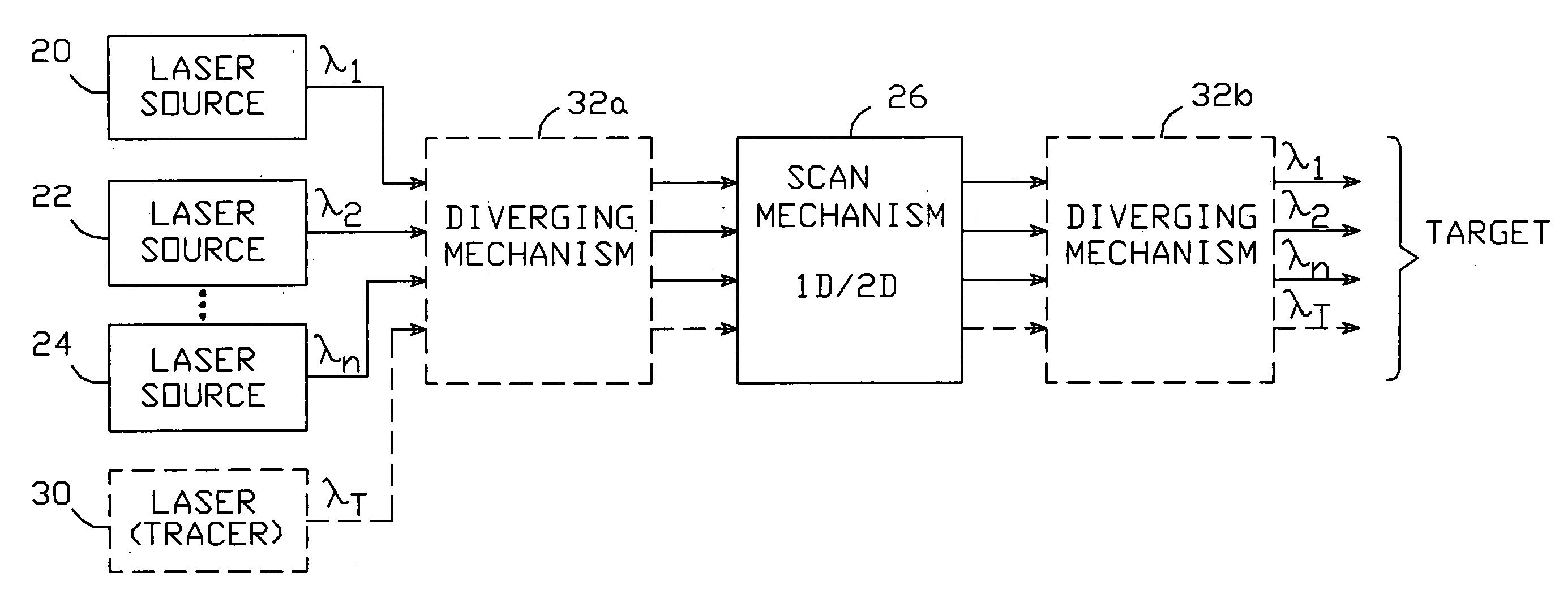
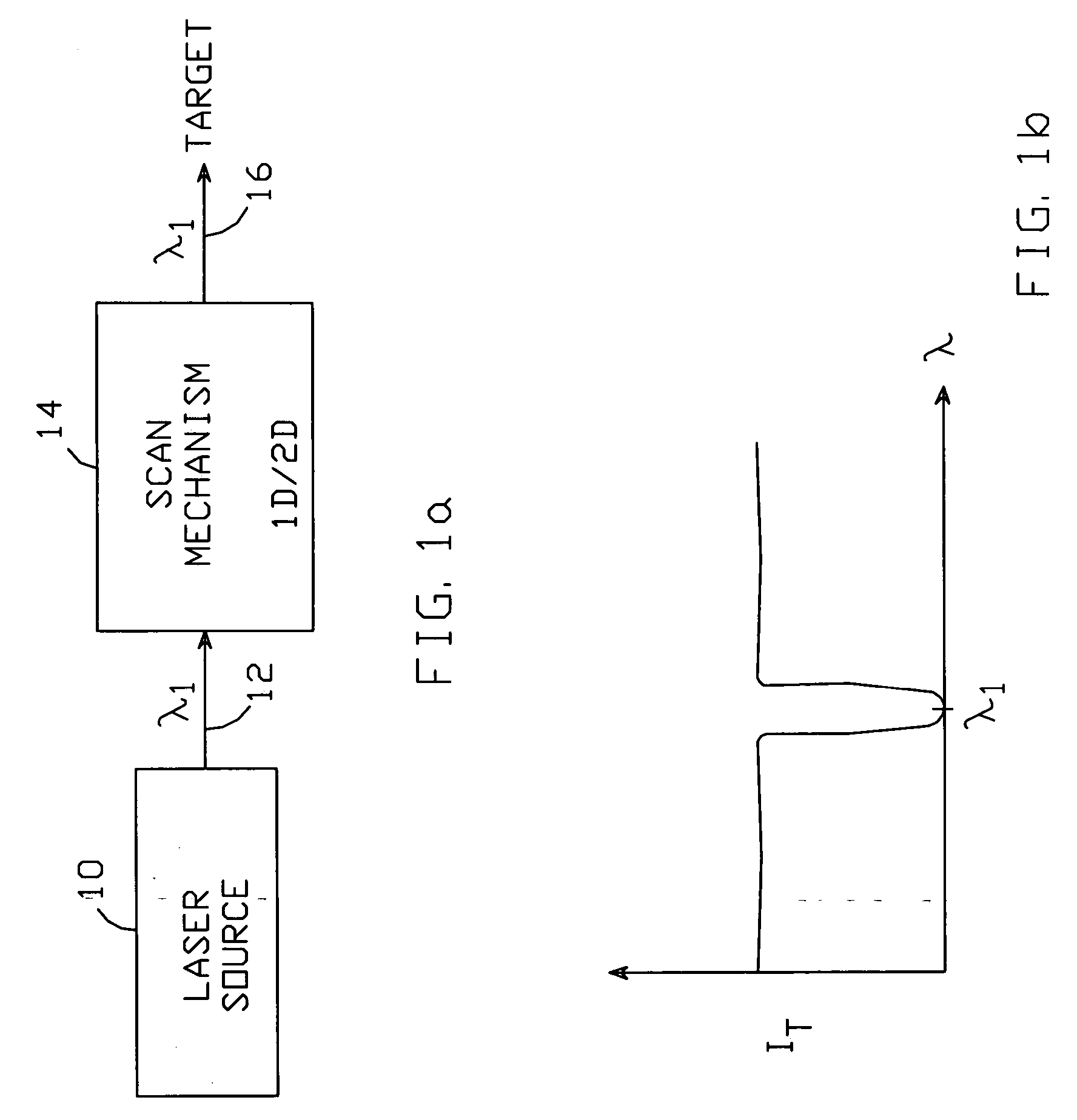
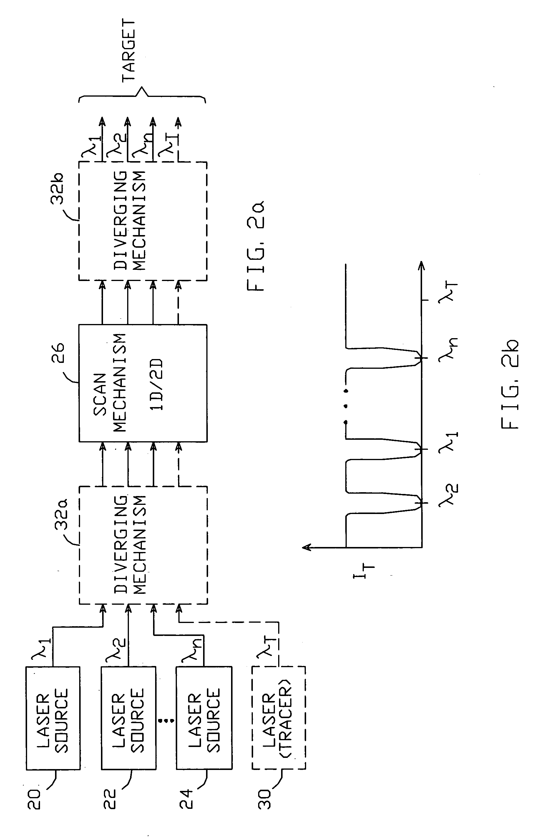
[0008] The system comprises two components. A laser light source generates visible laser light at one or more predetermined wavelengths. The light is designed such that it disorients and / or dazzles an opponent who sees the light with an unprotected eye. The system also includes an eye protection system which, when used by the operator and other associated personnel, substantially blocks light at the predetermined wavelengths, while being substantially transparent to visible light at other wavelengths—thereby allowing the operator to have the near-normal vision needed to successfully employ the system without also being disoriented by the generated light.
[0009] The laser light generated by the light source preferably has at least two predetermined wavelengths, with the eye protection system arranged to block light at each of the predetermined wavelengths while being substantially transparent to visible light at other wavelengths. The light source is arranged such that the fluence (i.e., energy / unit area) of the generated light does not cause permanent damage to the opponent's eyes. The generated laser light is scanned and / or diverged, to cover a large field of view, as well as to limit the light's fluence.

Problems solved by technology

However, none of these light- or laser-based systems provides a means of protecting those who employ such methods from the light, while simultaneously allowing those individuals to possess the near-normal vision needed to successfully employ the system.

Method used


Image

  • Non-lethal laser-based disorientation system
  • Non-lethal laser-based disorientation system
  • Non-lethal laser-based disorientation system

Examples


Embodiment Construction

[0017] The present non-lethal laser-based disorientation system comprises two portions: a laser light generation portion, and an eye protection portion. The laser light generation portion is intended to provide visible laser light having at least one predetermined wavelength. The laser light is directed to illuminate a target area, with the light having a fluence sufficient to disorient or dazzle a person within the target area whose vision is unprotected—but low enough to avoid causing permanent eye damage. The eye protection portion is matched to the laser light generation portion, such that the protection system substantially blocks light at the predetermined narrow wavelength, while being substantially transparent to visible light at other wavelengths. This enables the operators of the system to direct the laser light as needed, without them or their colleagues being dazzled or disoriented themselves. The laser light must be centered about wavelengths in the visible spectrum, so...


PUM


Abstract

A non-lethal laser-based disorientation system comprises a laser light source which generates visible laser light at one or more predetermined wavelengths. When directed by an operator at an opponent whose vision is unprotected, the light disorients and/or dazzles the opponent. The system also includes an eye protection system which substantially blocks light at the predetermined wavelengths, while being substantially transparent to visible light at other wavelengths. The light source is arranged such that the fluence of the generated light does not cause permanent damage to the opponent's eyes. The generated laser light is scanned and/or diverged, to cover a large field of view, as well as to limit the light's fluence. The eye protection system preferably comprises goggles worn by an operator and associated personnel, the lenses of which have an optical coating designed to block the predetermined wavelengths while being substantially transparent to visible light at other wavelengths.

Description

BACKGROUND OF THE INVENTION [0001] 1. Field of the Invention [0002] This invention relates to the field of systems for disorienting persons using light, and particularly to systems which dazzle and / or disorient using laser light while protecting those associated with the origin of the disorienting light. [0003] 2. Description of the Related Art [0004] Many non-lethal methods of overcoming a threatening and / or dangerous opponent have been developed, and are routinely employed by law enforcement, military personnel, and others. The objective of some of these methods is to distract or temporarily disable the opponent so that they may be captured, while minimizing casualties to those employing the methods. Tear gas, pepper spray, taser guns and rubber bullets are just a few examples. [0005] Several such methods involve the use of light to distract or disorient an opponent. For example, U.S. Pat. No. 5,837,918 to Sepp describes a rifle-like device that emits non-lethal laser light intend...

Claims


Application Information

Patent Timeline
Patent Type & Authority Applications(United States)
IPC IPC(8): B64D1/04F41H13/00
CPCF41H13/0056
Inventor RODE, JONATHAN P.
Owner TELEDYNE LICENSING
Why Eureka
Try Eureka