Tire building apparatus and assembly process

a technology of building apparatus and tire, which is applied in the field of tire building apparatus and assembly process, can solve the problems of substantial reduction of component parts, and achieve the effects of reducing the number of components, facilitating tire fabrication, and positive placement of bead reinforcemen

Inactive Publication Date: 2005-12-22
MICHELIN RECH & TECH SA
View PDF13 Cites 11 Cited by
  • Summary
  • Abstract
  • Description
  • Claims
  • Application Information

AI Technical Summary

Benefits of technology

[0006] The present invention relates to an apparatus that is used in the building of a tire and an assembly process for building a tire. The improved tire building apparatus has the dual advantages over previous inventions. First, the apparatus makes maximum use of substantially continuous support surfaces for the laying and manipulation of tire products. Second, the apparatus substantially reduces the number of component parts that require biaxial movement during the tire building process. In particular, the steps of posing a profiled rubber section on the carcass layer and fully folding the carcass layer are performed without expansion or retraction of the drum. The apparatus comprises an apparatus frame and a main shaft that is rotatable in at least one axis about the apparatus frame. The apparatus further comprises a building drum that is provided with a plurality of drum segments disposed concentrically about the axial center of the drum. The plurality of drum segments is movable in both the axial and radial directions and is fixed to the main shaft in rotation. Each of the plurali

Problems solved by technology

Second, the apparatus substantially reduces the number of component

Method used


Image

  • Tire building apparatus and assembly process
  • Tire building apparatus and assembly process
  • Tire building apparatus and assembly process

Examples


Embodiment Construction

[0031] Reference will now be made in detail to exemplary versions of the invention, one or more versions of which are illustrated in the drawings. Each described example is provided as an explanation of the invention, and not meant as a limitation of the invention. Throughout the description, features illustrated or described as part of one version may be usable with another version. Features that are common to all or some versions are described using similar reference numerals as further depicted in the figures.

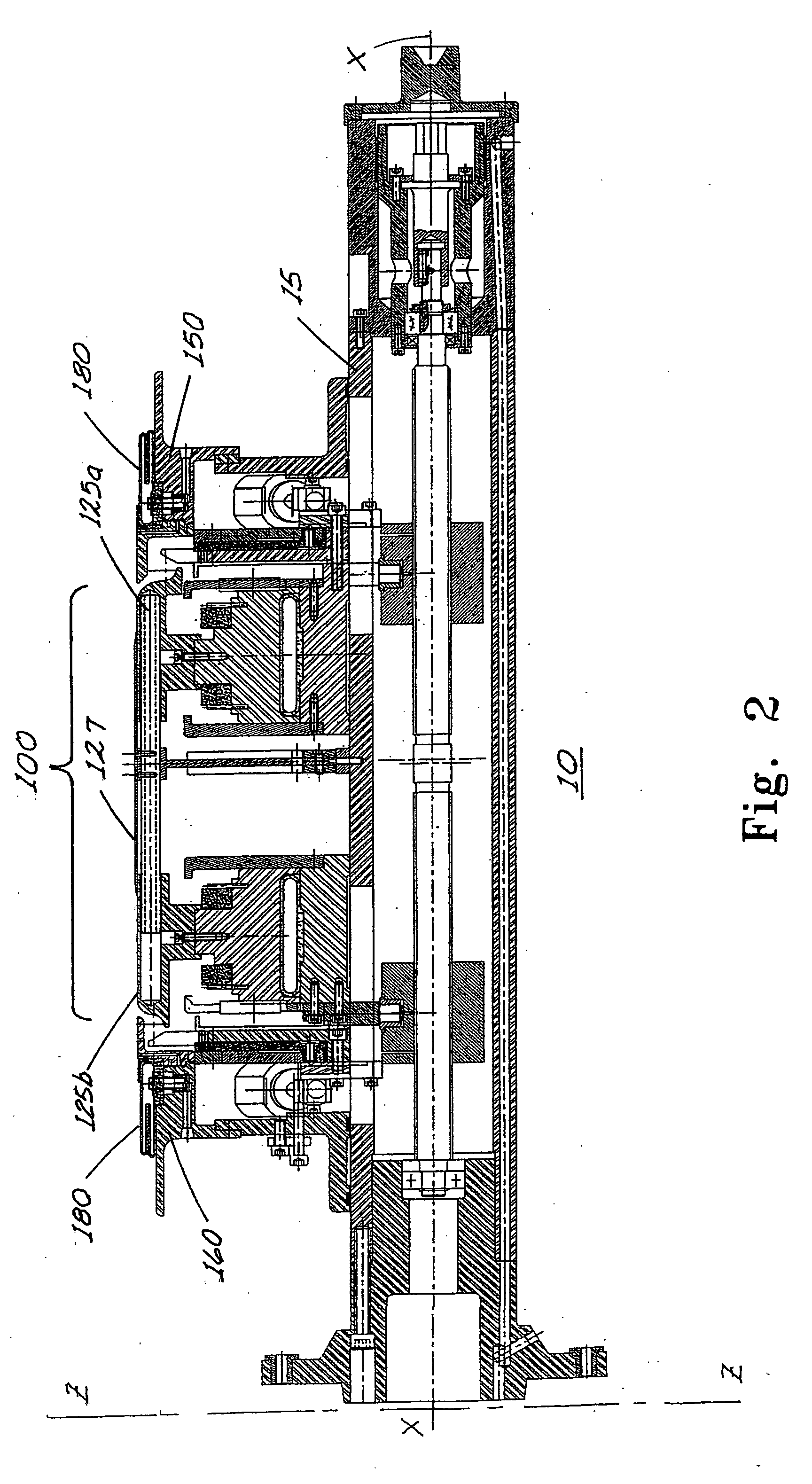
[0032]FIG. 2 depicts an apparatus 10 for building a tire corresponding to an embodiment of the invention comprising an apparatus frame 11 and a main shaft 15, a tire building drum 100, at least a right side assembly 150 and a left side assembly 160, The tire building drum 100 is configured for building tires having unequal bead diameters such as the tire shown in FIG. 1. The main shaft 15 of the apparatus is attached to the apparatus frame 11 so that the shaft can rotate at...


PUM

PropertyMeasurementUnit
Angleaaaaaaaaaa
Angleaaaaaaaaaa
Angleaaaaaaaaaa

Abstract

The present invention relates to an apparatus that is used in the building of a tire and an assembly process for building a tire. The apparatus comprises an apparatus frame and a main shaft that is rotatable in at least one axis about the apparatus frame. The apparatus further comprises a building drum that is provided with a plurality of drum segments disposed concentrically about the axial center of the drum and are movable in both the axial and radial directions and is fixed to the main shaft in rotation. The drum segments further comprise right and left shoulders located axially at the lateral edges, and the base of each of the shoulder extends axially to form a lateral projection. At least one version of the apparatus has right and left shoulders of unequal heights to facilitate fabrication of tires having unequal bead seat diameters. The apparatus further comprises at least a right and a left side assembly coaxially attached to the main shaft and located proximately to the lateral projection of the drum segments. When the side assemblies are positioned at the inward limit of axial extension, the surfaces of the drum segments and of the side assemblies form a substantially continuous cylindrical surface that supports the axial width of tire products to be assembled. The apparatus further comprises a plurality of lift tab segments positioned proximately to the drum segments

Description

TECHNICAL FIELD [0001] The present invention relates generally to a tire building apparatus and assembly process for building pneumatic tires. BACKGROUND [0002] Certain tires may have a bead architecture that is different from conventional pneumatic tires. The bead architecture may be designed in such a way that upon a loss of air pressure to the tire, the beads maintain an improved grip on the rim to better retain the tire on the rim than in conventional pneumatic tires. One design of this type of tire is illustrated in U.S. Pat. Nos. 5,785,781 and 5,971,047 that are owned by the assignee of the present invention and are incorporated by reference herein in their entirety for all purposes. FIG. 1 depicts an example of a tire having this bead architecture. See, for example, FIG. 2 of U.S. Pat. No. 5,971,047 for a detailed view of the bead construction. [0003] The construction of a pneumatic tire often involves a two-stage process. The first stage comprises the building of the beads a...

Claims


Application Information

Patent Timeline
IPC IPC(8): B29D30/18B29D30/24B29D30/32
CPCB29D30/248B29D2030/3207B29D30/32B29D30/24B29D30/30
Inventor LATIEYRE, JEAN-PIERRESATTERFIELD, LARRYDUPUIS, DANIEL ANDREBAILEY, DAVID WILLIAM
Owner MICHELIN RECH & TECH SA
Why Eureka
Try Eureka