
Metal packaging

a technology of metal packaging and metal parts, applied in the direction of tray containers, record carriers, container construction details, etc., can solve the problems of overwhelming demand in the market for such packaging, inability to provide packaging, and even bigger technical challenges

Active Publication Date: 2005-12-22
GLUD & MARSTRAND
View PDF46 Cites 20 Cited by
  • Summary
  • Abstract
  • Description
  • Claims
  • Application Information

AI Technical Summary

Benefits of technology

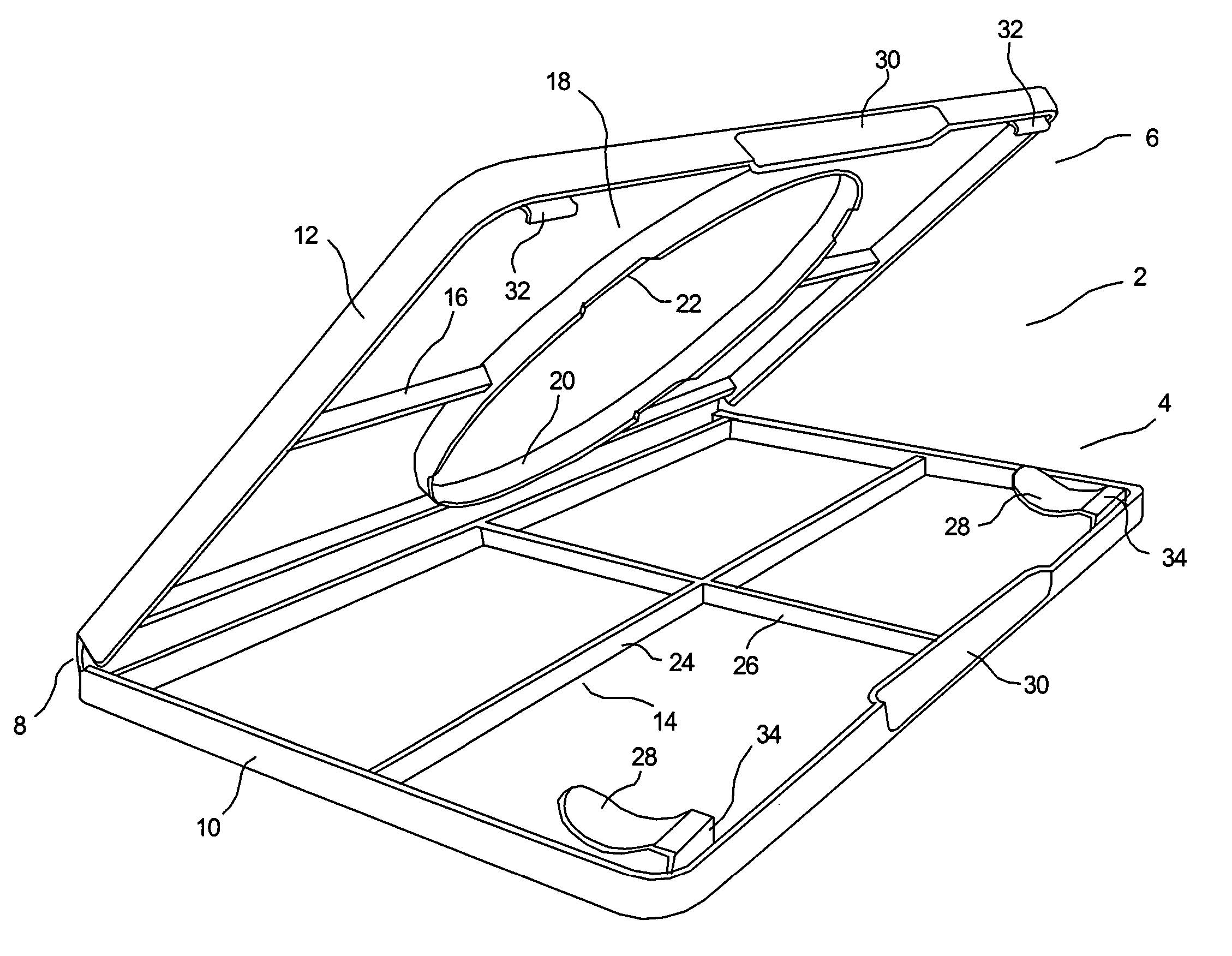
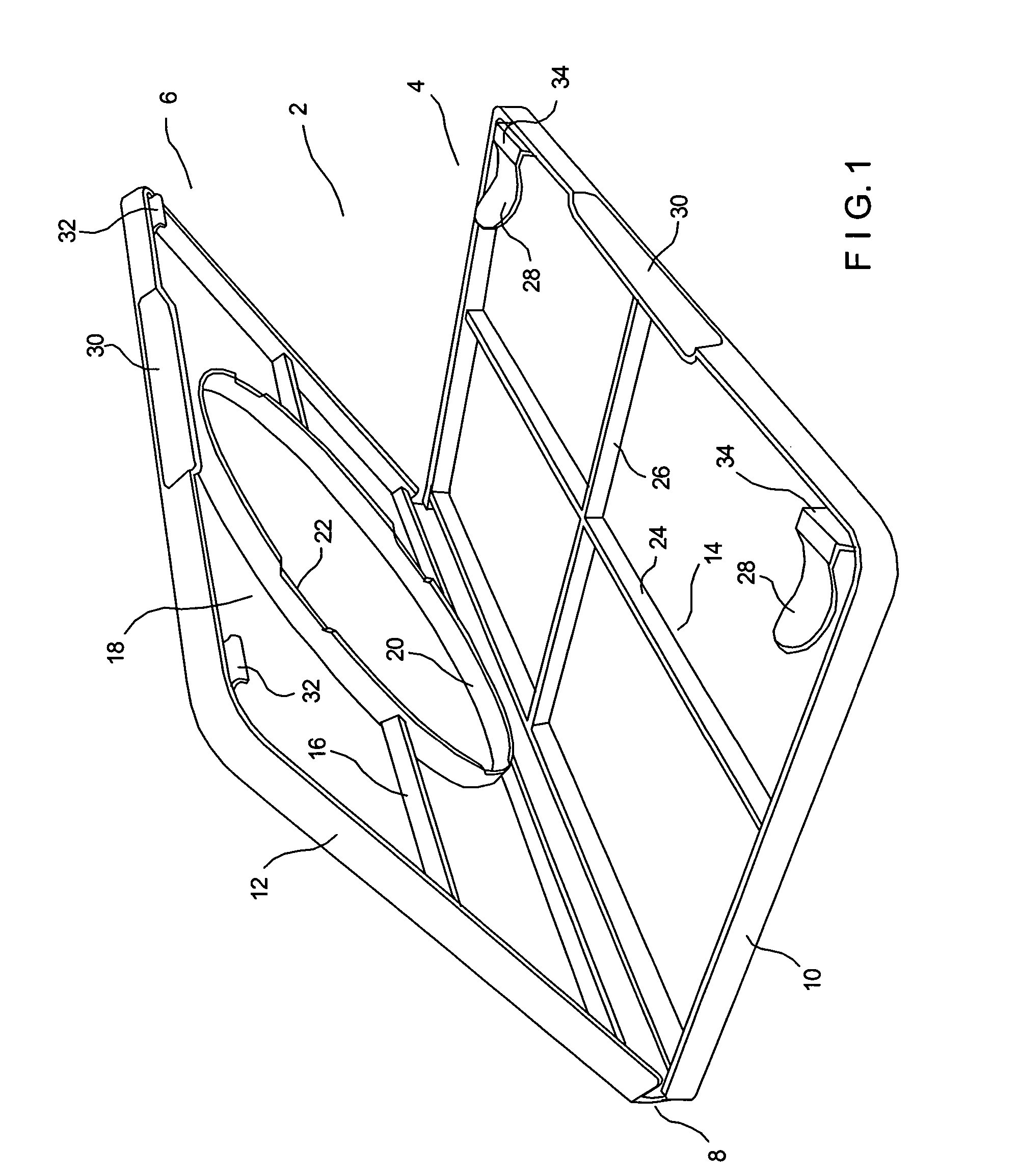
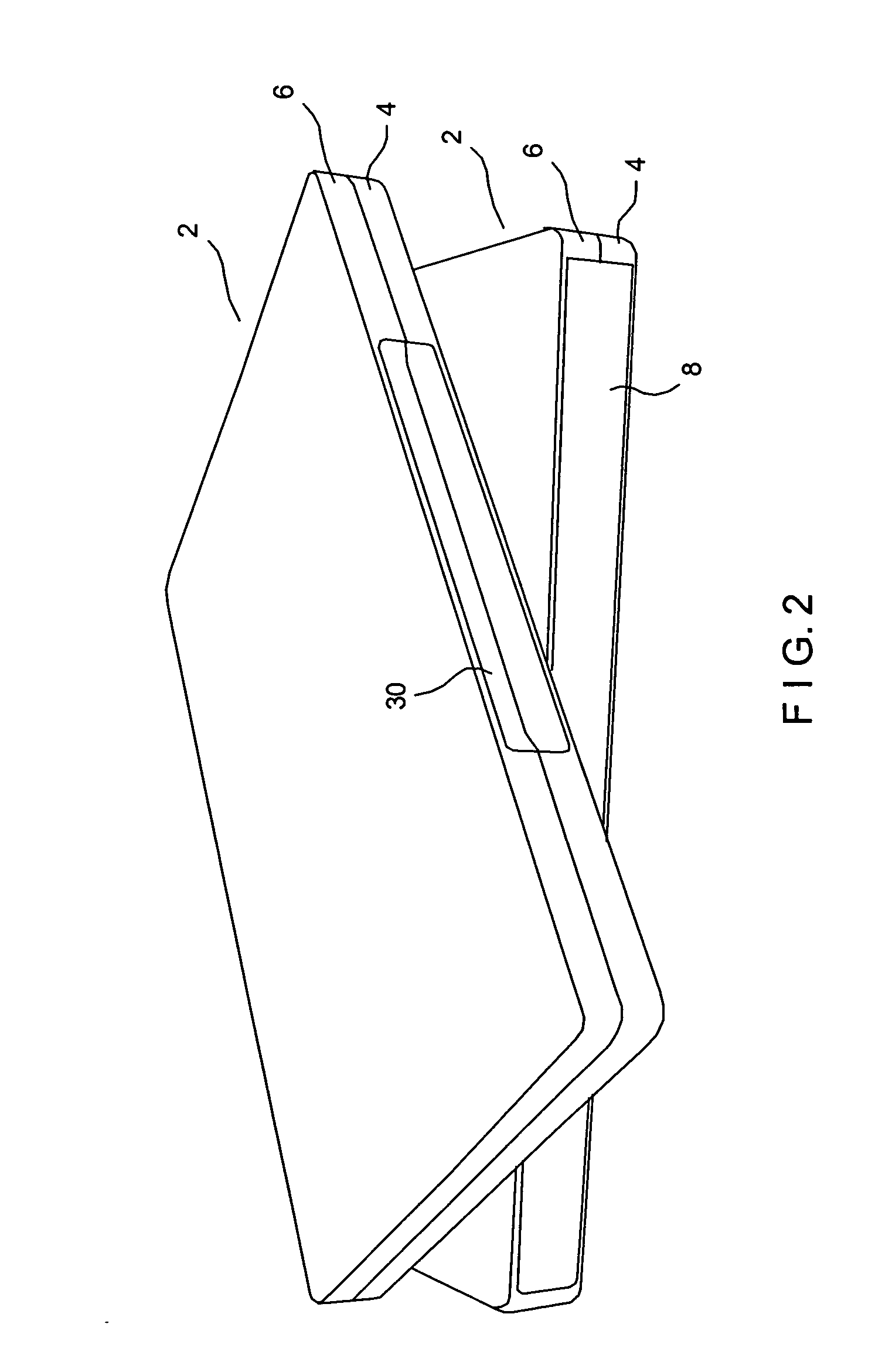
[0021] Generally, in order to achieve the above mentioned objectives a packaging consisting of outer metal parts attached to an inner part of non-metallic material with a hinge for opening the packaging is provided. This provides the freedom of design known from non-metal material, such as plastic, and the strength and exclusivity of metal, while still allowing the packaging to be packed in automated packing machine assemblies.

Problems solved by technology

However, all these many efforts have not led to metal packaging, which is capable of being packed in the standard automated packing machines commonly used in these industries for plastic packaging.
However, as stated the CD- and DVD-industries have not been able to provide a packaging that utilises these advantages, combined with the ability of being packed in the automated packing machines in the industries.
The demand in the market for such packaging is overwhelming, but the technical challenges even bigger.
However, these packaging systems can not be designed like a book due to the characteristics of the metal material.
The common characteristics of these systems is that they can not be designed like a book with the ability to open with an angle of more than 180°, preferably 240° due to the characteristics of i.a. the metal material and thus cannot be packed in the automated packing machines.

Method used


Image

  • Metal packaging
  • Metal packaging
  • Metal packaging

Examples


Embodiment Construction

[0021] Generally, in order to achieve the above mentioned objectives a packaging consisting of outer metal parts attached to an inner part of non-metallic material with a hinge for opening the packaging is provided. This provides the freedom of design known from non-metal material, such as plastic, and the strength and exclusivity of metal, while still allowing the packaging to be packed in automated packing machine assemblies.

[0022] Thus, according to a first aspect, the present invention relates to a packaging comprising;

[0023] a first and second outer part of metallic material,

[0024] an inner part of non-metallic material made in one piece and comprising; [0025] a first and second opposed side between which an element can be stored, [0026] a hinging part forming at least one hinge connecting said sides and allowing the sides to be rotated relative to each other within an angle so as to open the packaging and adapting the packaging for packing in an automated packing machine,

[...


PUM

PropertyMeasurementUnit
lengthaaaaaaaaaa
lengthaaaaaaaaaa
lengthaaaaaaaaaa

Abstract

A packaging comprising a first and second outer part of metallic material, an inner part of non-metallic material made in one piece and comprising a first and second opposed side between which an element can be stored and a hinging part forming at least one hinge connecting said sides and allowing the sides to be rotated relative to each other within an angle so as to open the packaging and adapting the packaging and adapting the packaging for packing in an automated packing machine. At least a part of a perimeter of the first and second outer part is adapted to retain the inner part in order to attach said outer parts to said respective sides of said inner part for covering substantial part of the outer surfaces of the sides.

Description

FIELD OF THE INVENTION [0001] The present invention relates to metal packaging for storing elements, such as data-carrying elements like Compact Discs or DVDs, which packaging is adapted to be packed in automated packing machines for plastic packaging. BACKGROUND OF THE INVENTION [0002] The CD and DVD industries have for decades invested substantial sums of money in developing metal packaging. However, all these many efforts have not led to metal packaging, which is capable of being packed in the standard automated packing machines commonly used in these industries for plastic packaging. [0003] The total sum of investments in such automated packing machinery is huge and the total number of packaging, produced in the CD- and DVD- industries, exceeds 5 billion pieces per year. [0004] Metal as a component of packaging for CDs, DVDs and other forms of media gives a large number of advantages, including supplying the packaging with substantially additional strength and giving an exclusiv...

Claims


Application Information

Patent Timeline
Patent Type & Authority Applications(United States)
IPC IPC(8): G11B33/04
CPCG11B33/0427G11B33/0422G11B23/03G11B23/02G11B23/023
Inventor BJERREGAARD, JANABOLFAZLIAN, MAZYARZUBCEVIC, ESADMIKKELSEN, POULMADSON, CHRISTIAN ORUMBRIX, TORSTENJORGENSEN, NIELS TOFT
Owner GLUD & MARSTRAND
Learn More