Hoisting device with load measuring mechanism and method for determining the load of hoisting devices

a hoisting device and load measurement technology, applied in the field of hoisting devices, can solve the problems of heightening the speed and accuracy of measurement, and achieve the effects of accurate measurement, precise and reliable results, and low wear and tear

Inactive Publication Date: 2005-12-22
TEREX MHPS
View PDF12 Cites 14 Cited by
  • Summary
  • Abstract
  • Description
  • Claims
  • Application Information

AI Technical Summary

Benefits of technology

[0028] The sensors may have noncontact operation, so that wear and tear and disturbances from impurities are minimized.
[0029] One embodiment of the sensor on the shaft calls for a holder at least partly embracing the shaft. Thus, e.g., two detectors or coils sensitive to magnetic field can be arranged on opposite sides of the shaft, so that two measurement signals are produced, allowing for a more accurate measurement and possibly correction of the signals from environmental influences.
[0030] More precise and reliable results may be obtained when 2 to 8, especially 2, 4 or 8 detectors or coils sensitive to magnetic field are provided for each region and uniformly arranged about the region. Then, in particular, a redundant connection of the sensor or coils and evaluation of their signals can also be performed.

Problems solved by technology

The gear transmission, however, is especially attractive, since the shafts have a slight material thickness there, which heightens the speed and accuracy of the measurement.

Method used


Image

  • Hoisting device with load measuring mechanism and method for determining the load of hoisting devices
  • Hoisting device with load measuring mechanism and method for determining the load of hoisting devices
  • Hoisting device with load measuring mechanism and method for determining the load of hoisting devices

Examples


Embodiment Construction

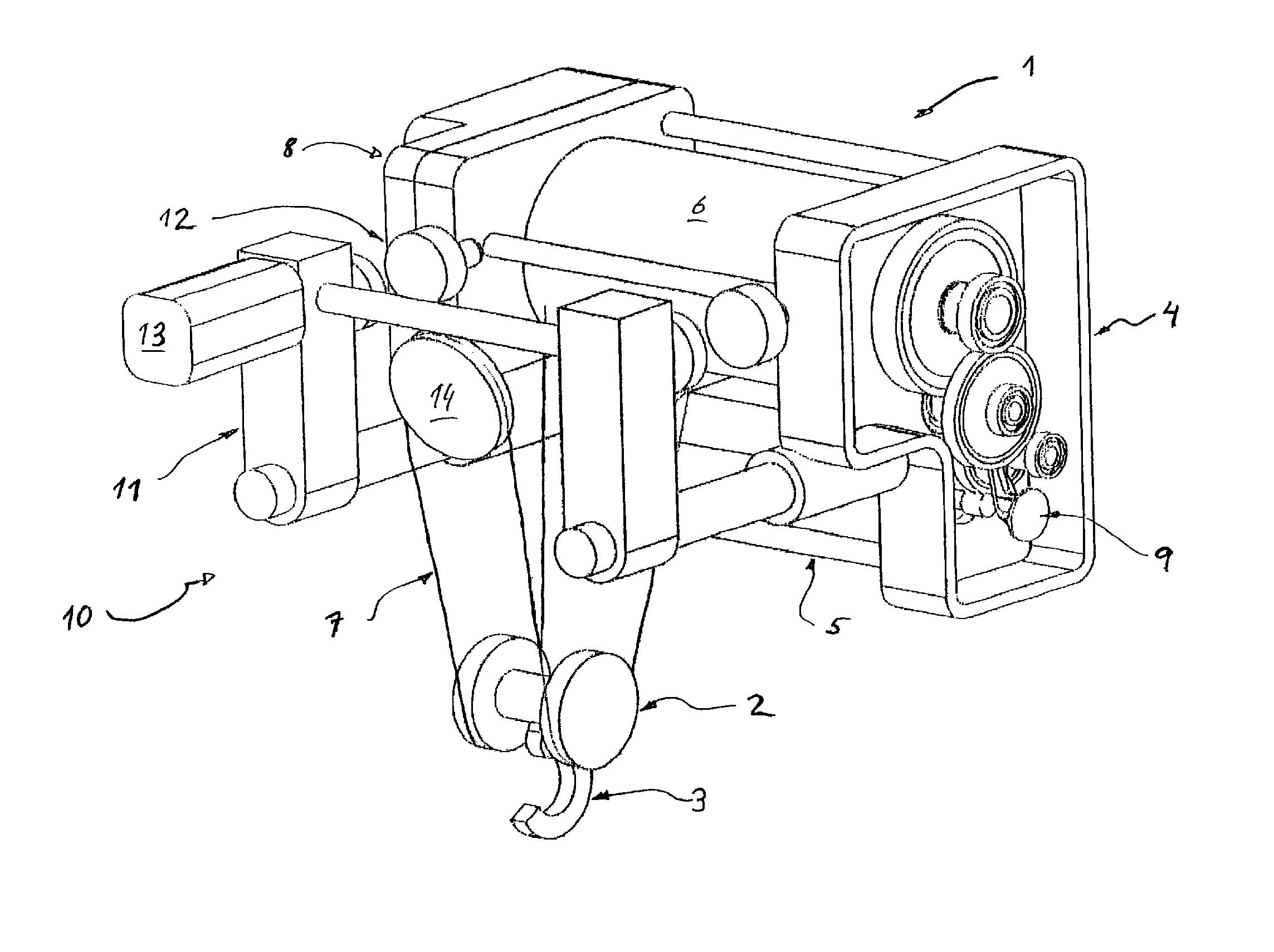
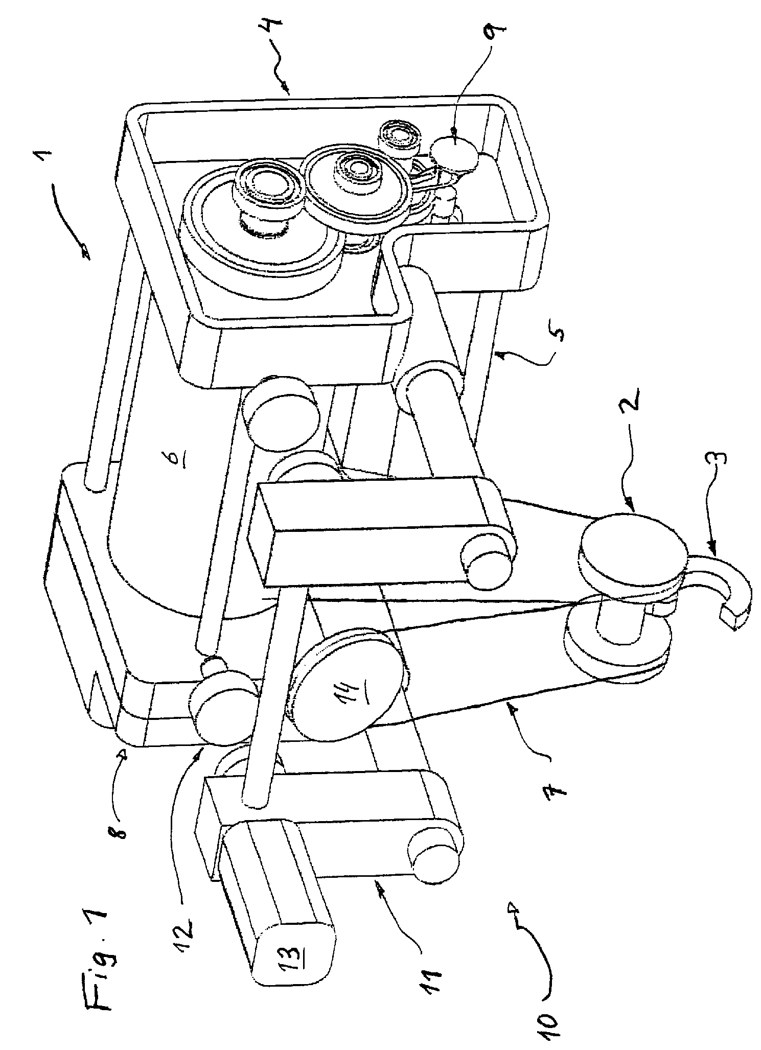
[0038]FIG. 1 shows a single-rail trolley, designated overall as 10, with a frame 11 and a hoisting mechanism 1 secured to it. For travel on the lower flange of a rail (not shown), the single-rail trolley 10 has four rollers 12, which lie opposite each other in pairs, one of them being driven by a motor 13.

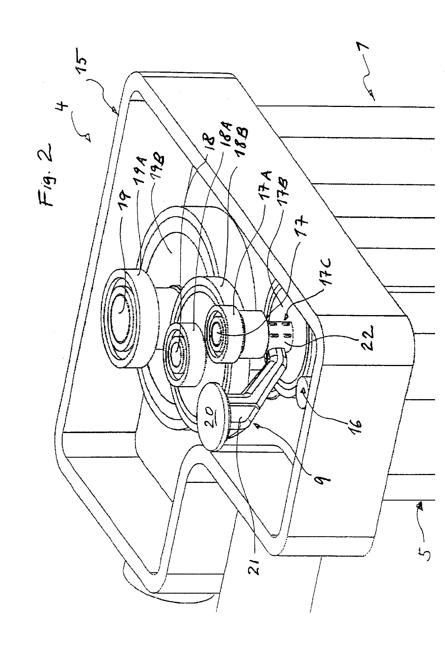
[0039] A hoisting mechanism 1 is provided that includes a cable drum 6, driven by a motor 5 across a transmission 4, the transmission 4 being arranged on one side of the cable drum 6 and electronic controls 8 on the opposite side. The transmission 4 comprises a load measuring sensor 9 on one of its intermediate shafts.

[0040] A cable 7 is wound around the drum 6, being led across a deflection roller 14 and a bottom block 2 with hook 3. A load suspended from the hook 3 is raised and lowered by winding and unwinding the cable 7 on the drum 6 by corresponding controls of the motor 5.

[0041] Thus, depending on the particular static and kinematic relations and the reeving used, as well...


PUM

PropertyMeasurementUnit
torqueaaaaaaaaaa
magnetostrictionaaaaaaaaaa
permanent magnetizationaaaaaaaaaa

Abstract

A hoisting device, especially a cable or chain block, with a hoisting transmission having at least one shaft and with a hoisting load measuring mechanism. In order to determine the hoisting load as accurately as possible and possibly independent of the reeving and without additional structural height, the hoisting load has at least one sensor for detecting the deformation of the shaft produced by the hoisting load and the detected deformation is used as a quantity in determining the hoisting load.

Description

BACKGROUND OF THE INVENTION [0001] The invention concerns a hoisting device, especially a cable or chain block, with a gearing having at least one shaft and with a load measuring mechanism. [0002] Hoisting devices like cable or chain blocks have a predetermined lifetime, which depends on the load stress and the load frequency distribution. Furthermore, an economical use of hoisting devices requires a high capacity utilization. In order to determine the remaining lifetime each year, one therefore requires, at a minimum, the hours of operation and their load frequency distribution as data. [0003] Formerly, the data needed to determine the hours of operation and the load frequency distribution were gathered manually or estimated. However, this is time-consuming and inaccurate. Methods and devices were therefore developed to automatically count the hours of operation, so-called operating hour counters. Corresponding methods and devices for monitoring of hoisting devices are known, for e...

Claims


Application Information

Patent Timeline
Patent Type & Authority Applications(United States)
IPC IPC(8): B66C13/16B66D1/50G01L3/10
CPCB66D1/50B66C13/16
Inventor KOHLENBERG, THOMASSCHULTE, FRANZ
Owner TEREX MHPS
Why Eureka
Try Eureka