Power-up reset circuit

a power-up reset and circuit technology, applied in electronic switching, pulse technique, instruments, etc., can solve the problems of increased power consumption of power-up reset circuit b>100/b>, difficult to interpret voltage levels (e.g., high and/or low voltage levels) within semiconductor memory devices, and power voltage may not be completely stabl

Inactive Publication Date: 2005-12-22
SAMSUNG ELECTRONICS CO LTD
View PDF6 Cites 24 Cited by
  • Summary
  • Abstract
  • Description
  • Claims
  • Application Information

AI Technical Summary

Benefits of technology

[0027] An example embodiment of the present invention is directed to a power-up reset circuit, including a first resistance adjuster including a first resistor and a first transistor, the first transistor in parallel with the first resistor and r

Problems solved by technology

While the semiconductor memory device undergoes the power-up operation, the power voltage may not be completely stable.
The instability of the power voltage may make it difficult to interpret voltage levels (e.g., high and/or low voltage levels) within the semiconductor memory device.
The power-up reset circuit 100 may have increased power consumption due to a standby current flowing through the power voltage detecting portion 10 during a normal operation.
Further, when a power dip (i.e., a temporarily reduced power voltage Vcc) occurs during a normal operation, an abnormal (e.g., unstable) operation of the conventional semiconductor memory device may occur (e.g., since the reset signal VCCH may transi

Method used


Image

  • Power-up reset circuit
  • Power-up reset circuit
  • Power-up reset circuit

Examples


Embodiment Construction

[0038] Hereinafter, example embodiments of the present invention will be described in detail with reference to the accompanying drawings.

[0039] In the Figures, the same reference numerals are used to denote the same elements throughout the drawings.

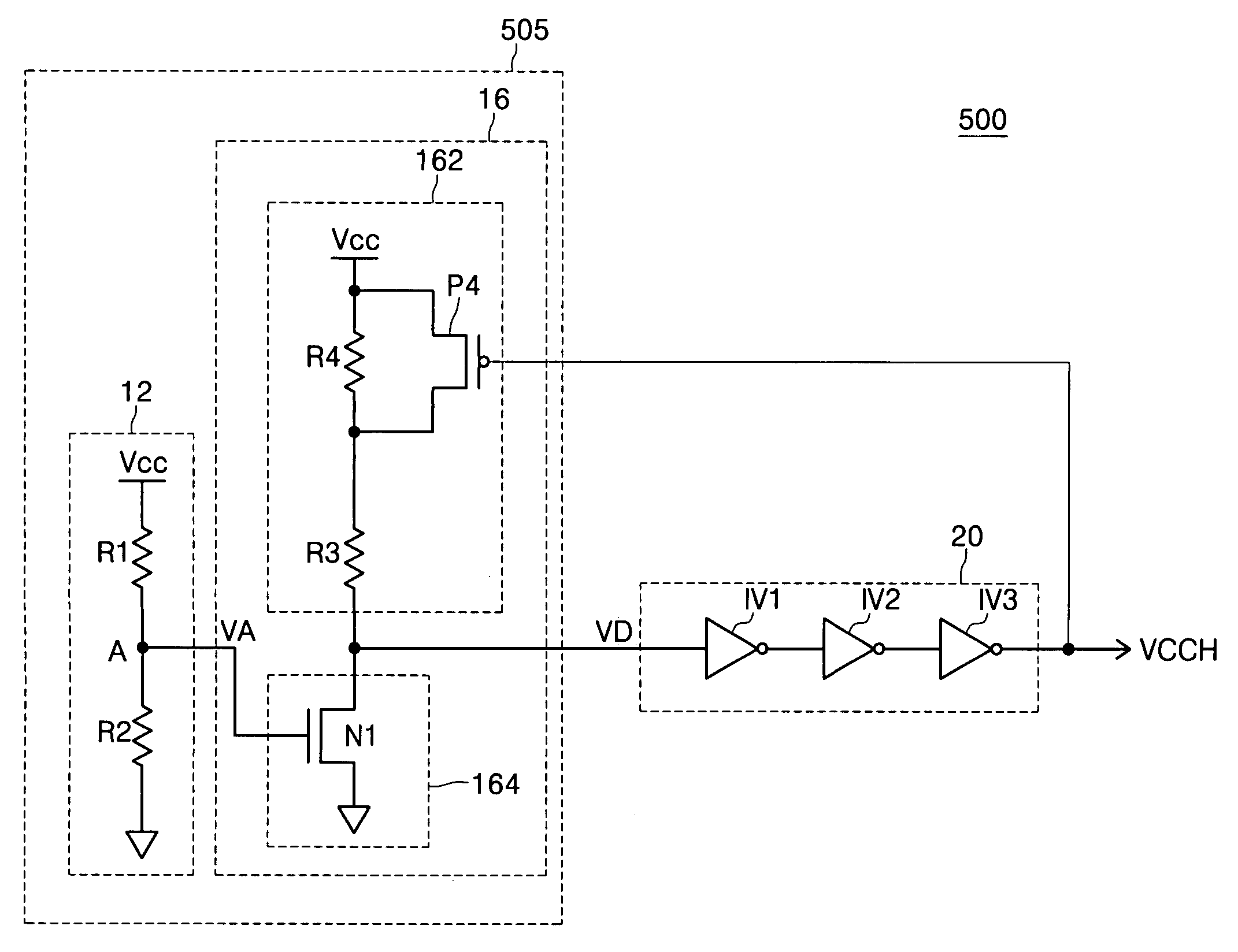
[0040] FIG 5 is a block diagram illustrating a power-up reset circuit 500 according to an example embodiment of the present invention. The power-up reset circuit 500 may include a power voltage detecting portion 505 and a signal generating portion 20. The power voltage detecting portion 505 may include a detecting portion 12 and an output portion 16. The output portion 16 may include a pull-up 162 and a pull-down 164. The pull-up 162 may include resistors R3 and R4 and a PMOS transistor P4. The pull-down 164 may include an NMOS transistor N1.

[0041] In one example embodiment of the present invention, the power voltage detecting portion 505 may detect a power voltage Vcc and may output a voltage detecting signal VD.

[0042] In one example...


PUM


Abstract

A power-up reset circuit with reduced power consumption. The resistance of the power-up reset circuit may be adjusted during a power-up operation. The standby current may thereby be reduced, which may reduce the power consumption in the power-up reset circuit.

Description

CROSS-REFERENCE TO RELATED APPLICATION [0001] This application claims the benefit of Korean Patent Application No. 2004-45688, filed Jun. 18, 2004, the disclosure of which is hereby incorporated herein by reference in its entirety. BACKGROUND OF THE INVENTION [0002] 1. Field of the Invention [0003] The present invention relates generally to a power-up reset circuit, and more particularly, to a power-up reset circuit for reducing power consumption. [0004] 2. Description of the Related Art [0005] A power-up operation may include a power voltage applied to a semiconductor memory device. While the semiconductor memory device undergoes the power-up operation, the power voltage may not be completely stable. The instability of the power voltage may make it difficult to interpret voltage levels (e.g., high and / or low voltage levels) within the semiconductor memory device. When the power voltage is first applied during power-up, the semiconductor memory device may require initialization. Thu...

Claims


Application Information

Patent Timeline
IPC IPC(8): H03K17/00G11C5/14H03K17/22H03L7/00
CPCH03K2217/0036H03K17/223G11C5/14
Inventor SHIN, CHANG-HOKIM, NAM-JONG
Owner SAMSUNG ELECTRONICS CO LTD
Why Eureka
Try Eureka