Eureka AIR delivers breakthrough ideas for toughest innovation challenges, trusted by R&D personnel around the world.

Focus detection method and focus detection apparatus

a detection method and focus technology, applied in the field of focus detection methods and focus detection apparatuses, to achieve the effect of high probability and secure determination of the credibility of peak contrast values

Inactive Publication Date: 2005-12-22
RICOH IMAGING COMPANY
View PDF4 Cites 34 Cited by
  • Summary
  • Abstract
  • Description
  • Claims
  • Application Information

AI Technical Summary

Benefits of technology

[0006] The present invention provides a focus detection method which makes it possible to detect a peak contrast value (maximum contrast value) with a high probability even when object contrast is low in a focus detection apparatus for detecting a focus state in accordance with image contrast so that the credibility of the peak contrast value can be securely determined from the magnitude of the contrast. The present invention further provides a focus detection apparatus adopting such a focus detection method.
[0016] Furthermore, according to the present invention, when a peak value of contrast is determined to detect a focused focal point, the credibility of the peak contrast value can be reliably determined for even a low-contrast object image because a criterial value for determining the credibility of the peak contrast value is set to a high value in the case of a normal object image and is set to low value in the case of a low-contrast object image.

Problems solved by technology

Additionally, there is a possibility of the peak value of contrast in a low-contrast object image being determined as not being credible if the peak value (maximum value) of contrast is detected in each of a low-contrast object image and a normal object image using common criterion because the credibility of the detected peak value of contrast is determined from the magnitude of the contrast in the conventional contrast detection method.

Method used


Image

  • Focus detection method and focus detection apparatus
  • Focus detection method and focus detection apparatus
  • Focus detection method and focus detection apparatus

Examples


Embodiment Construction

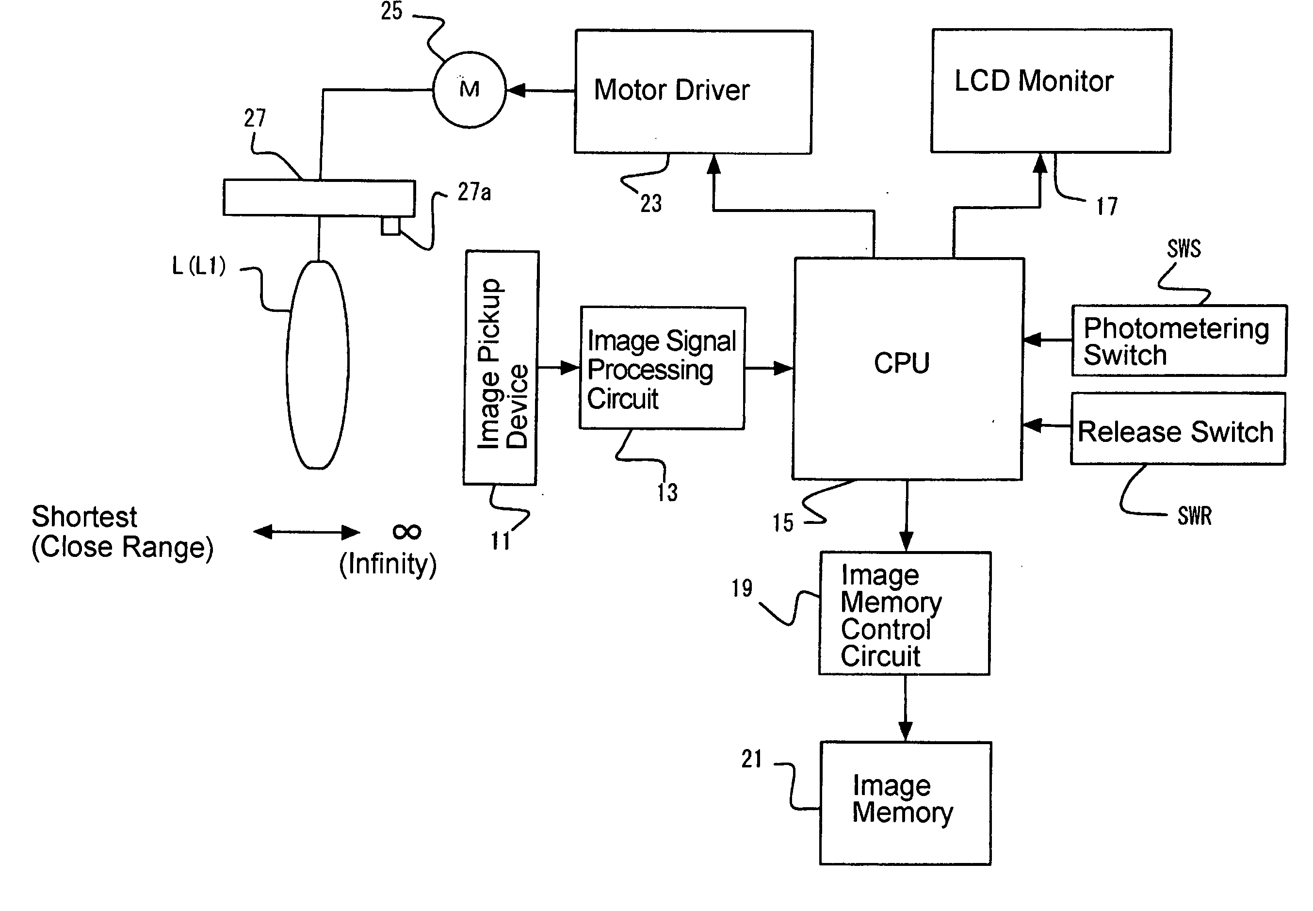
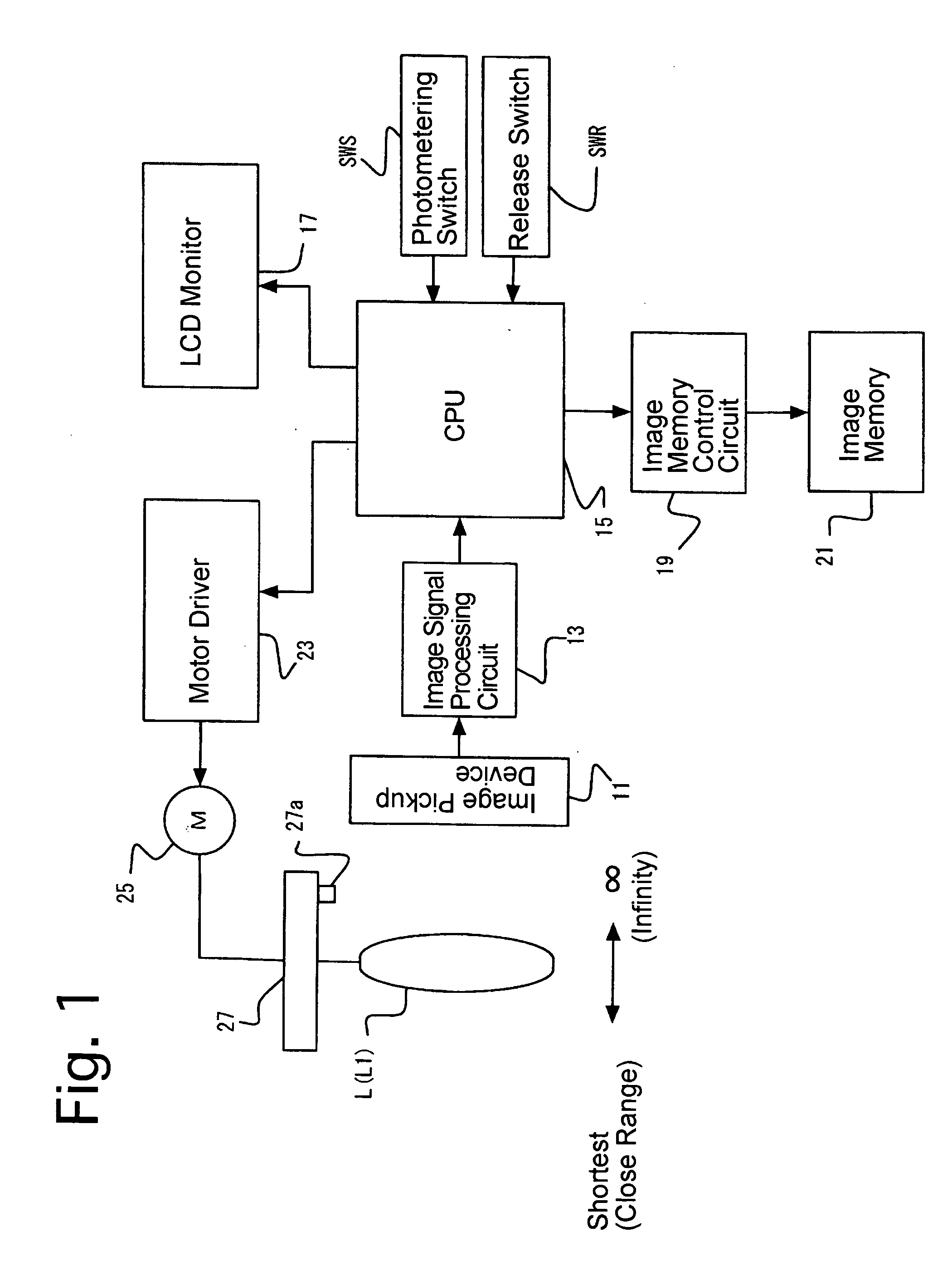
[0030]FIG. 1 is a block diagram of an embodiment of a digital camera to which the present invention is applied.

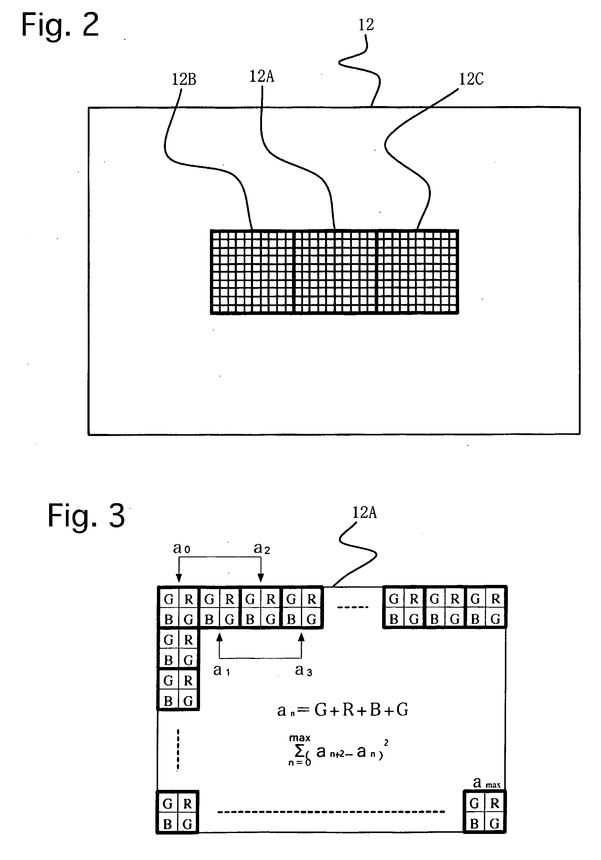
[0031] The digital camera is provided with a photographing lens L including a focusing lens group L1, and an image pickup device (CCD image sensor) 11 serving as an imaging device. An object image is formed on a light receiving surface 12 (see FIG. 2) of the image pickup device 11 via the photographing lens L. The image pickup device 11 includes a large number of pixels (photoelectronic transducing elements) arranged in a two-dimensional matrix at predetermined intervals. The digital camera is further provided with an image signal processing circuit 13, a CPU (controller) 15, an LCD monitor 17, an image memory control circuit 19, an image memory 21, a motor driver 23, an AF motor 25 and a lens drive mechanism 27. Each pixel of the image pickup device 11 converts the incident light of an object image thereon into an electrical charge, and the electrical charges is accumulat...


PUM


Abstract

A focus detection apparatus includes a focusing lens group, and a controller. The controller establishes a first predetermined number and a first criterial value if a maximum contrast value and / or minimum contrast value is outside a predetermined range, and a second predetermined number and second criterial value if the maximum and minimum contrast values are within the predetermined range; compares contrast values detected at adjacent positions to determine whether the contrast value of the object image increases once and subsequently decreases by the first or second predetermined number of times; detects a maximum contrast value if the contrast value of the object image increases once and subsequently decreases by the first or second predetermined number of times; determines a difference between the maximum contrast value and a detected contrast value; and selects the maximum contrast value if the difference exceeds the first / second criterial value.

Description

BACKGROUND OF THE INVENTION [0001] 1. Field of the Invention [0002] The present invention relates to a focus detection method for detecting the focus state of a digital camera on an object in accordance with the contrast of an image thereof captured by the digital camera. The present invention also relates to a focus detection apparatus using such a focus detection method. [0003] 2. Description of the Related Art [0004] A contrast detection method is known as a conventional focus detection method for compact AF digital cameras. Conventional focus detection apparatuses using the contrast detection method operate to determine the position of a focusing lens group in which contrast of an object image captured by an image pickup device becomes maximum. Therefore, in such conventional focus detection apparatuses, an imaging operation is performed successively at different positions of the focusing lens group while the focusing lens group is driven stepwise from the infinite focus positio...

Claims


Application Information

Patent Timeline
Patent Type & Authority Applications(United States)
IPC IPC(8): H04N5/232
CPCH04N5/23212H04N23/673
Inventor NAKAHARA, NAOTO
Owner RICOH IMAGING COMPANY
Why Eureka
Eureka Blog
Learn More