Image capturing apparatus and focusing control method

a technology of image capture and control method, applied in the field of image capture apparatus and focusing control method, can solve the problem of lack of credibility of phase difference af method, and achieve the effect of high speed

Active Publication Date: 2015-08-11
FUJIFILM CORP
View PDF9 Cites 17 Cited by
  • Summary
  • Abstract
  • Description
  • Claims
  • Application Information

AI Technical Summary

Benefits of technology

[0009]An illustrative aspect of the present invention is to provide an image capturing apparatus that may determine the credibility of a phase difference AF method at high speed.
[0012]With any one of [1] and [2], it is possible to provide an image capturing apparatus and a focusing control method that may determine the credibility of a phase difference AF method at high speed.

Problems solved by technology

It has been known that the phase difference AF method lacks credibility when a high frequency component is included in an image of a subject.

Method used


Image

  • Image capturing apparatus and focusing control method
  • Image capturing apparatus and focusing control method
  • Image capturing apparatus and focusing control method

Examples


first modified example

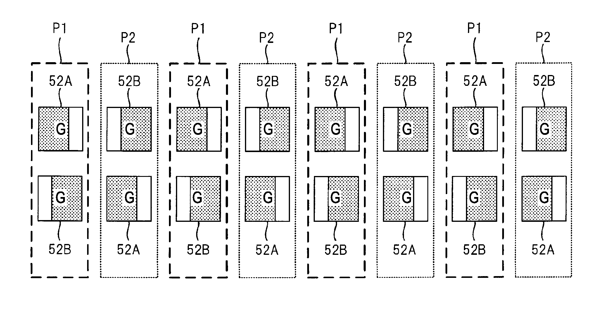
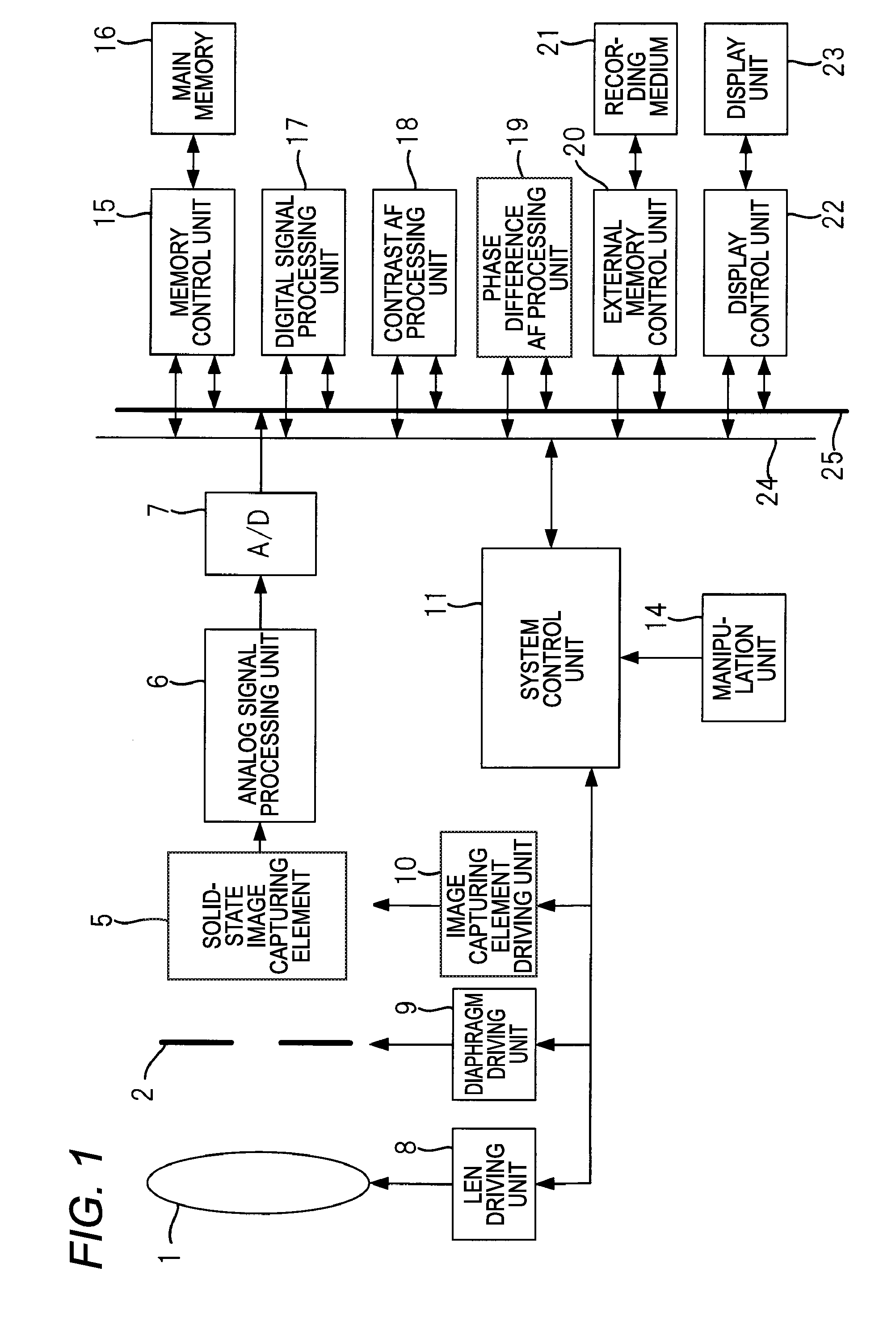
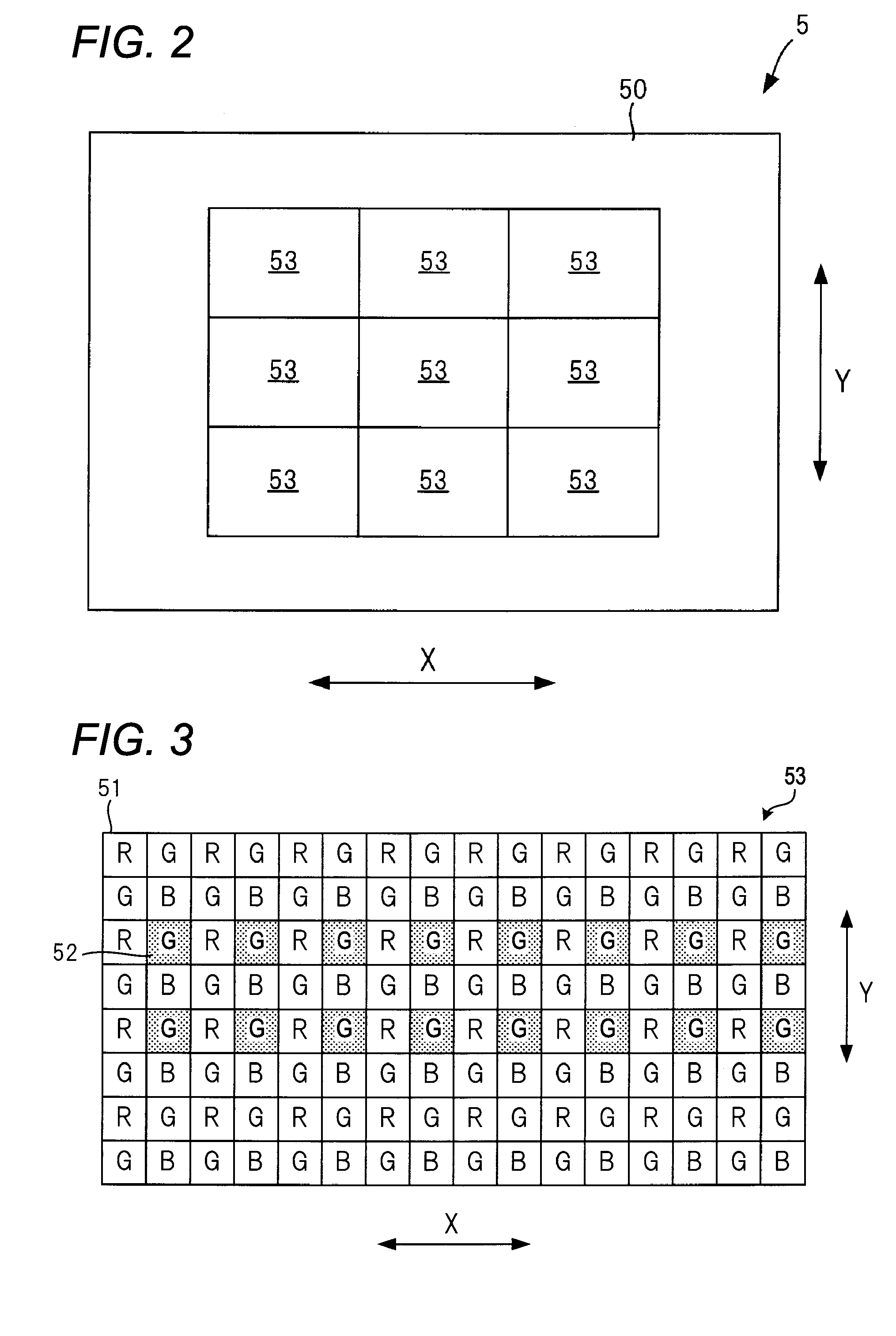
[0175]FIG. 11 is a view illustrating a modified example of an arrangement of phase difference detection pixels 52A and 52B present in the AF area 53 of the solid-state image capturing element 5 illustrated in FIG. 1.

[0176]In the example of the arrangement illustrated in FIG. 11, two phase difference pixel lines, each of which includes a plurality of the phase difference detection pixels 52A parallel in the row direction X, and two phase difference pixel lines, each of which includes a plurality of the phase difference detection pixels 52B parallel in the row direction X, are formed in the AF area 53, and the credibility determination is performed by setting four phase difference pixel lines as one block. In the meantime, all the pixels located at the same position in the row direction X within the block are located adjacently with each other to the extent that light from the same portion of the subject is received.

[0177]In one block illustrated in FIG. 11, each phase difference dete...

second modified example

[0185]FIG. 12 is a view illustrating another modified example of an arrangement of phase difference detection pixels 52A and 52B present in the AF area 53 of the solid-state image capturing element 5 illustrated in FIG. 1.

[0186]In the example of the arrangement illustrated in FIG. 12, two phase difference pixel lines, each of which includes a plurality of the phase difference detection pixels 52A parallel in the row direction X and two phase difference pixel lines, each of which includes a plurality of the phase difference detection pixels 52B parallel in the row direction X, are formed in the AF area 53, and the credibility determination is performed by setting four phase difference pixel lines as one block. In the meantime, all the pixels located at the same position in the row direction X within the block are located adjacently with each other to the extent that light from the same portion of the subject is received.

[0187]In one block illustrated in FIG. 12, each phase difference...

third modified example

[0194]FIG. 13 is a view illustrating another modified example of an arrangement of phase difference detection pixels 52A and 52B present in an AF area 53 of the solid-state image capturing element 5 illustrated in FIG. 1.

[0195]In the example of the arrangement illustrated in FIG. 13, two phase difference pixel lines, each of which includes a plurality of the phase difference detection pixels 52B parallel in the row direction X and one phase difference pixel line which includes a plurality of the phase difference detection pixels 52A parallel in the row direction X, are formed in the AF area 53 and the credibility determination is performed by setting three phase difference pixel lines as one block. In the meantime, all the pixels located at the same position in the row direction X within the block are located adjacently with each other to the extent that light from the same portion of the subject is received.

[0196]In the example of the arrangement illustrated in FIG. 13, each phase ...


PUM


Abstract

An image capturing apparatus, includes: an image capturing element configured to capture an image of a subject; and a focusing control unit configured to perform a focusing control by a phase difference AF method using detection signals of first signal detection units and second signal detection units; a matching degree generation unit configured to generate a first matching degree which corresponds to a matching degree of two images captured by a first pair using the detection signals of the respective signal detection units of the first pair, and a second matching degree which corresponds to a matching degree of two images captured by a second pair using the detection signals of the respective signal detection units of the second pair; and a credibility determination unit configured to determine credibility of the focusing control by the phase difference AF method based on the first matching degree and the second matching degree.

Description

CROSS-REFERENCE TO RELATED APPLICATIONS[0001]This application is based on and claims priority under 35 U.S.C. 119 from Japanese Patent Application No. 2013-195890 filed on Sep. 20, 2013, the entire content of which is incorporated herein by reference.BACKGROUND[0002]1. Technical Field[0003]The present invention relates to an image capturing apparatus and a focusing control method.[0004]2. Related Art[0005]In recent years, as the resolution of the solid-state image capturing elements, such as the CCD (Charge Coupled Device) image sensor or the CMOS (Complementary Metal Oxide Semiconductor) image sensor is becoming more and more enhanced, demand for an information equipment having photographing function, such as, for example, a digital still camera, a digital video camera, a mobile phone such as a smart phone, or a PDA (Personal Digital Assistant, portable information terminal), is rapidly increasing. In the meantime, the information equipment having image capturing function described...

Claims


Application Information

Patent Timeline
Patent Type & Authority Patents(United States)
IPC IPC(8): H04N5/225H04N5/374H04N5/232H04N5/372
CPCH04N5/23212H04N5/374H04N5/372H04N5/3696H04N23/672H04N25/704H04N25/134H04N25/71H04N25/76
Inventor AOKI, TAKASHI
Owner FUJIFILM CORP
Why Eureka
Try Eureka