
Gas turbine airfoil trailing edge corner

Active Publication Date: 2005-12-22
SIEMENS ENERGY INC
View PDF18 Cites 29 Cited by
  • Summary
  • Abstract
  • Description
  • Claims
  • Application Information

AI Technical Summary

Problems solved by technology

One of the problems facing designers of airfoils exposed to hot combustion gases is that the airfoils need to be sufficiently strong to withstand forces applied to it during operation of the gas turbine, yet still retain an ability to be cooled effectively to prevent thermal fatigue.
Reducing an amount of material used to form the airfoil, such as by making airfoil walls thinner, may reduce an amount of a cooling fluid flow required, but using less material to form the airfoil may adversely reduce a strength of the airfoil.
Conversely, increasing an amount of material used to form the airfoil may make the airfoil stronger, but reduce the ability of the airfoil to be cooled sufficiently to prevent thermal fatigue.
However, a thin trailing edge may increase the likelihood of failure of the trailing edge, for example, under the high centrifugal stresses imposed on it during turbine operation.

Method used


Image

  • Gas turbine airfoil trailing edge corner
  • Gas turbine airfoil trailing edge corner
  • Gas turbine airfoil trailing edge corner

Examples


Embodiment Construction

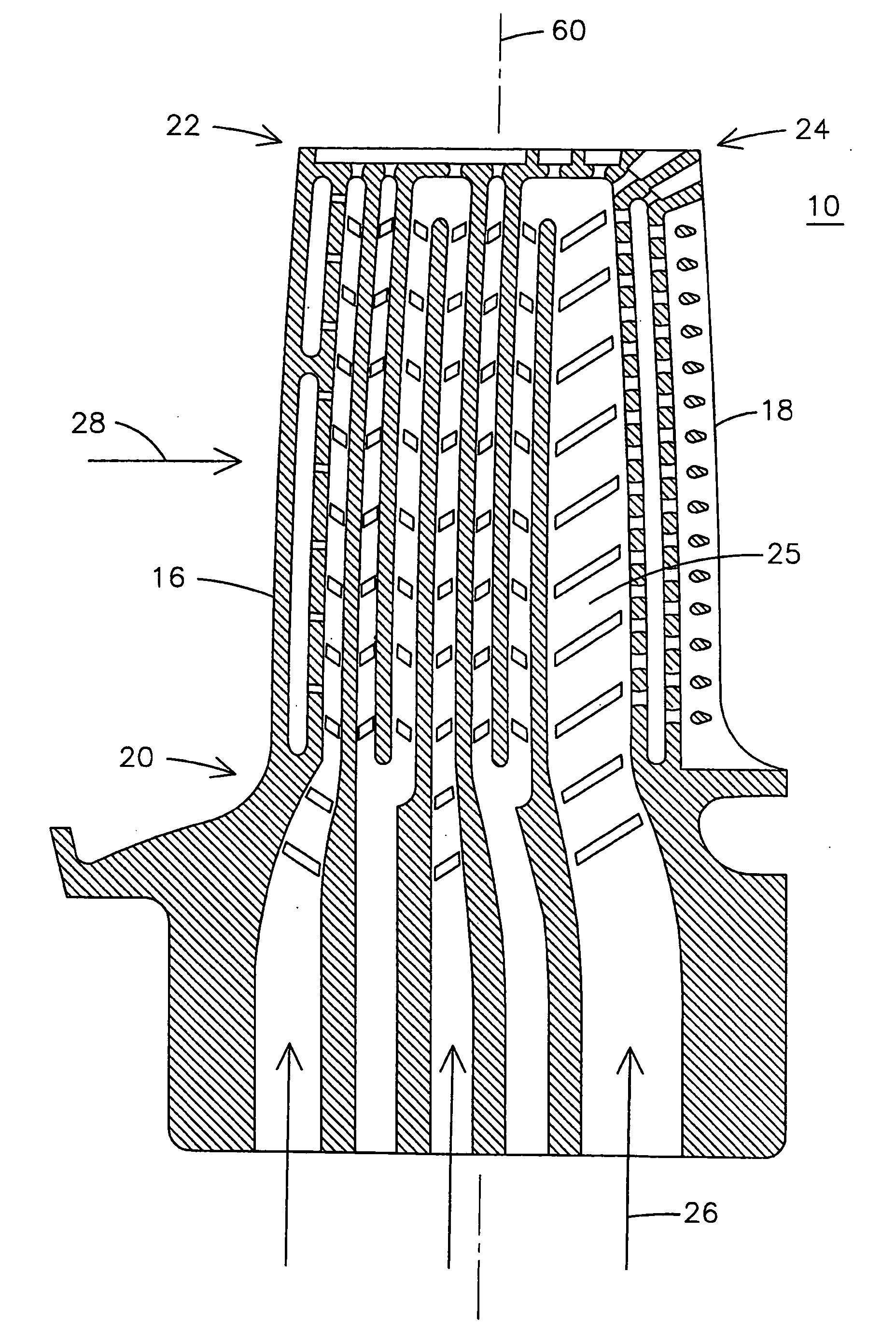
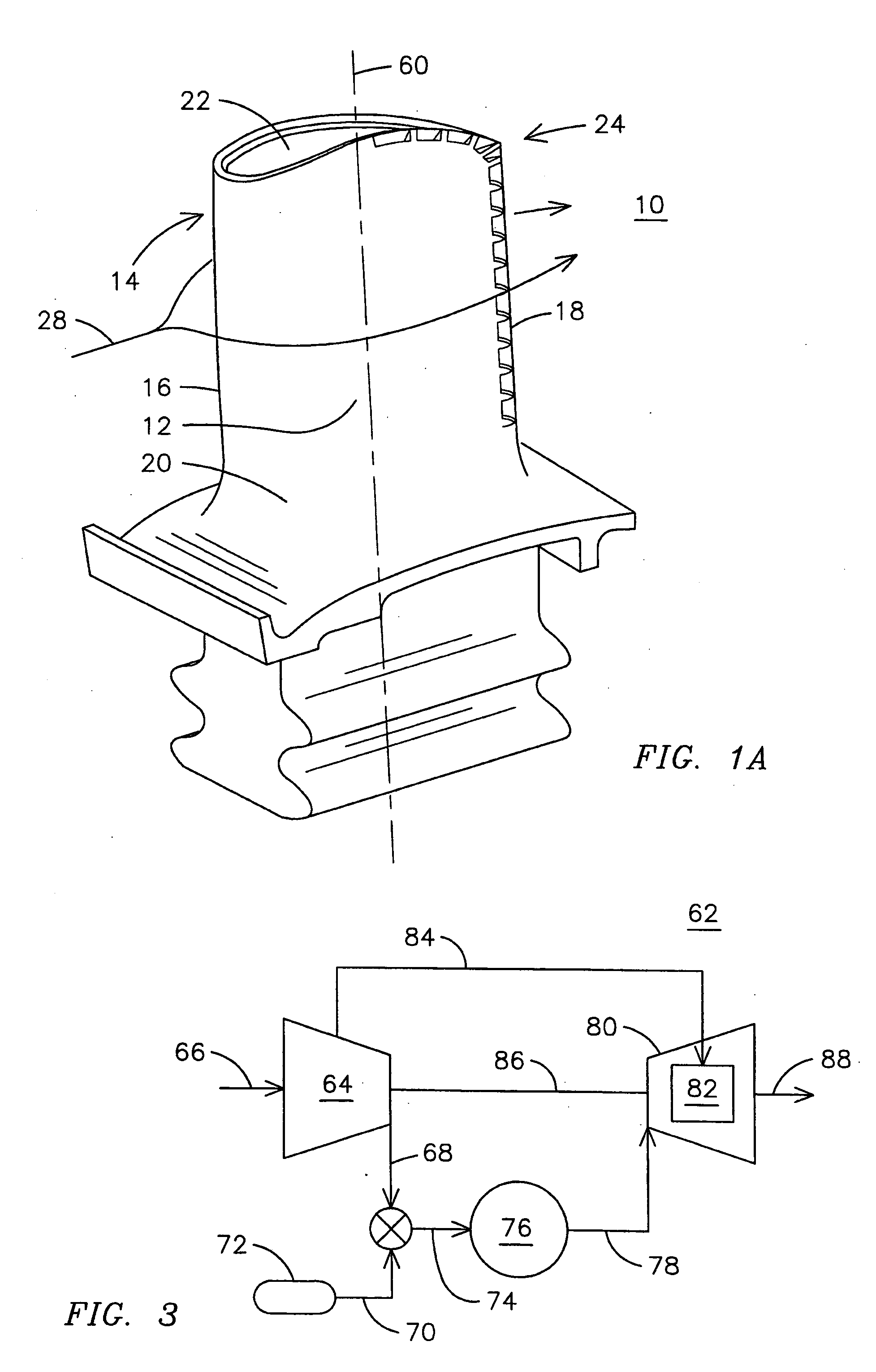
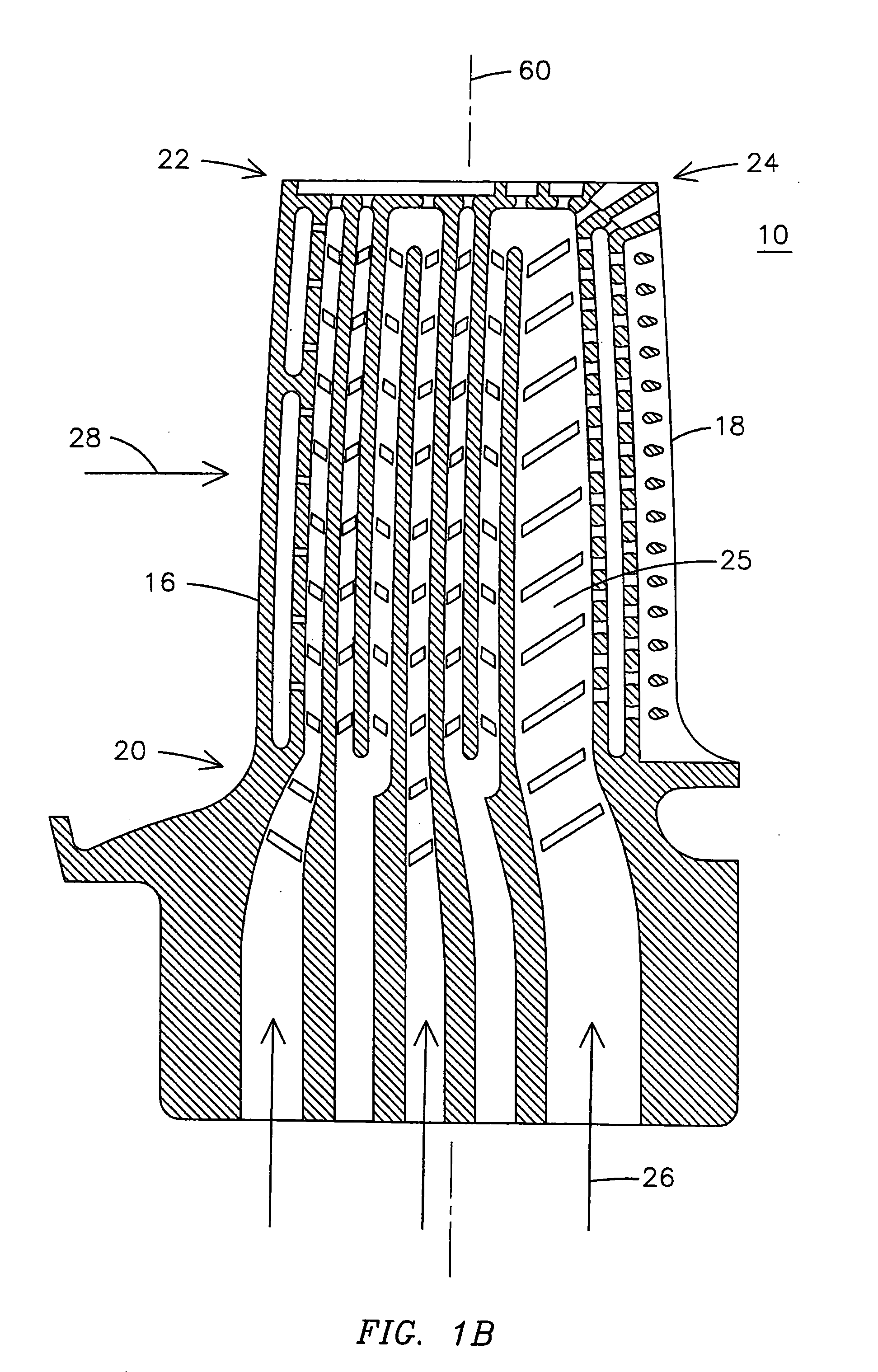
[0009]FIG. 1A is a perspective view of a turbine airfoil 10 having an improved trailing edge corner configuration and FIG. 1B is a cross-sectional view of the turbine airfoil 10 of FIG. 1A taken along a radial axis 60 of the airfoil 10. Generally, the airfoil 10 includes a pressure sidewall 12 and a suction sidewall 14 joined along respective leading 16 and trailing edges 18 and extending radially outward from a root 20 to a tip 22. A trailing edge corner 24 defines an intersection of the trailing edge 18 and the tip 22. The airfoil 10 may include an internal serpentine cooling passage 25 having an inlet in the root 20 into which a cooling fluid flow 26 may be injected. During gas turbine operation, a hot combustion fluid flow 28 flows around an exterior of the airfoil 10.

[0010] To achieve aerodynamic efficiency, the trailing edge of a gas turbine airfoil is typically tapered to a relatively thin apex. However, the trailing edge of the airfoil, and, in particular, the trailing edge...


PUM


Abstract

A gas turbine airfoil (10) includes a pressure sidewall (12) and a suction sidewall (14) joined along respective leading (16) and trailing edges (18) and extends radially outward from a root (20) to a tip (22). The airfoil also includes a trailing edge corner (24) comprising a metering hole (36) receiving a cooling fluid flow (26) from an interior fluid flow channel (e.g., 32) and discharging a metered flow (40). A dispersion cavity (42) receives the metered flow and discharges a dispersed flow (44). The dispersion cavity includes a cross sectional area (46) greater than a cross sectional area (48) of the metering hole. An open flow channel (52) receives the dispersed flow and conducts the dispersed flow to a periphery (54) of the airfoil, the open flow channel controlling mixing of the cooling fluid flow with a process gas (e.g., 28) flowing around an exterior (34) of the airfoil.

Description

FIELD OF THE INVENTION [0001] This invention relates generally to gas turbines engines, and, in particular, to an improved gas turbine airfoil trailing edge corner. BACKGROUND OF THE INVENTION [0002] Gas turbine airfoils exposed to hot combustion gases have been cooled by forming passageways within the airfoil and passing a cooling fluid through the passageways to convectively cool the airfoil. Such cooled airfoils may include a serpentine, multiple-pass flow path to provide sufficient convective cooling to maintain all portions of the airfoil at a relatively uniform temperature. In addition, the cooling fluid flow may be allowed to exit an interior of the airfoil at desired locations to provide film cooling of an external surface of the airfoil. One of the problems facing designers of airfoils exposed to hot combustion gases is that the airfoils need to be sufficiently strong to withstand forces applied to it during operation of the gas turbine, yet still retain an ability to be co...

Claims


Application Information

Patent Timeline
IPC IPC(8): F01D5/18F01D5/20
CPCF01D5/20F01D5/187
Inventor LIANG, GEORGE
Owner SIEMENS ENERGY INC
Learn More