Method and apparatus for the removal and handling of honey frames from beehive boxes

a technology for beehives and frames, applied in the field of apiculture, can solve the problems of difficult access for beekeepers to the edges of the top plate of the frame, extreme complexity of most automated systems, and hardly suitable individual beekeepers, so as to facilitate the removal of the frame and increase the force

Inactive Publication Date: 2005-12-22
POINTER WILLIAM
View PDF11 Cites 9 Cited by
  • Summary
  • Abstract
  • Description
  • Claims
  • Application Information

AI Technical Summary

Benefits of technology

[0019] It is therefore an object of the present invention to provide a system and method for the removal, handling, and inspection of honey frames from beehive boxes. The system includes a handle bar that may be positioned along the edge of and parallel with the top plate of the improved honey frame of the present invention. The handle bar retains two threaded bolts that are aligned with threaded apertures that have been positioned in the top plate of the honey frame. The threaded bolts are secured within the threaded apertures into a spaced attachment to the improved frame. Once positioned in this manner, the propolis may be cut from the frame top plate as necessary, and the frame lifted from the hive by the beekeeper's handling of the handle bar. Although the beekeeper may wish to cut the propolis away to facilitate the removal of the frame it should be noted that the system of the present invention greatly reduces or eliminates the need for such work preparatory to the removal of the improved frame. This is due to the increased force that may be exerted on the frame to extract it from the box without concern that that handle will be released from the frame. Once the frame is removed from the box, the tubular handle bar is configured to be inserted into a clamping device that may be positioned at an appropriate height on and over a table or other structure. The clamping device grips at least one end of the handle bar of the system and retains the handle bar and the attached frame in a position appropriate for inspection. The clamping device permits the beekeeper to turn the frame within the clamp at any angle desired for progressive inspection of the entire honeycomb.

Problems solved by technology

In most cases, however, it is difficult for a beekeeper to access these edges of the top plate of the frame to even initially lift the frame from the hive.
Many of these tools involve complex automated devices designed to extract the entire set of frames from a box, and maneuver the frames across a conveyer to a point where the honey is extracted.
While these may be appropriate for the industrial sized beekeeping business or facility, they are hardly appropriate for the individual beekeeper, who works on a small scale, or as a hobby.
In addition the extreme complexities of most of the automated systems lend themselves to constant maintenance and repair as well as cleaning.
The device of the Wilson patent, however, suffers from a number of drawbacks.
First, and perhaps most importantly, the user must constantly exert clamping force on the tool in order to extract the frame from the hive, as well as while manipulating the frame for inspection or harvesting.
The beekeeper must generally cut the propolis away from the frame, otherwise the tool cannot grip the frame tightly enough to forcibly extract the frame from the hive box.
This greatly limits the ability of the beekeeper to work with the honeycomb within the frame without damaging or dropping the frame altogether.
In addition, the pliers type clamp of the Wilson device does not provide an easy way of inspecting the honeycomb once it is removed from the hive.
Manipulating the holder system while still clamping the device on the frame would prove to be quite difficult.

Method used


Image

  • Method and apparatus for the removal and handling of honey frames from beehive boxes
  • Method and apparatus for the removal and handling of honey frames from beehive boxes
  • Method and apparatus for the removal and handling of honey frames from beehive boxes

Examples


Embodiment Construction

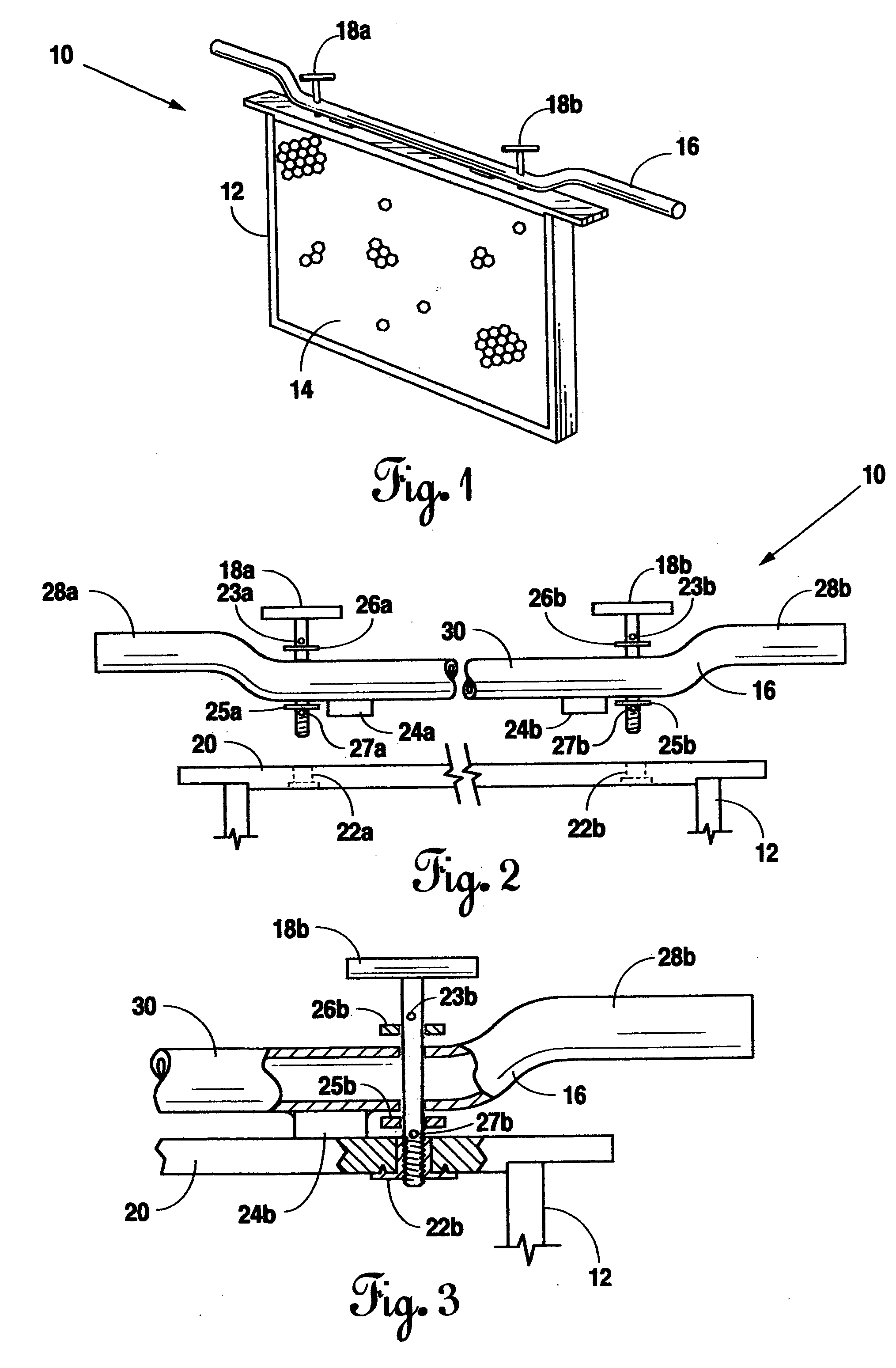
[0025] Reference is made first to FIG. 1 for a description of the basic structure of the present invention and the manner in which it is attached to the improved honey frame. Frame handle 10 is positioned as shown on hive frame 12 containing foundation 14. Frame handle 10 comprises handle bar 16 and T-bolts 18a and 18b. Handle bar 16 may, in the preferred embodiment, be constructed of tubular metal bent into the configuration shown so as to provide for easing gripping by the beekeeper. Its length should be somewhat longer than the standard honey frame, and its width should be slightly less than the typical width of a honey frame top plate.

[0026] Two or more T-bolts 18a and 18b are positioned through handle bar 16 with the winged portions of the bolts positioned above the handle bar. In this manner, the threaded portions of T-bolts 18a and 18b are positioned to engage threaded apertures (not shown) that have previously been positioned within the top plate of frame 12.

[0027]FIG. 2 s...


PUM


Abstract

A system and method for the removal, handling, and inspection of honey frames from beehive boxes. The system includes a handle bar positioned on the top plate of an improved frame structure. The handle bar retains two threaded T-bolts that are aligned with threaded aperture inserts that have been positioned in the top plate to form the improved honey frame. The threaded bolts are secured within the threaded aperture inserts to a spaced attachment to the frame. Once positioned, excess top wax is scraped away and the frame lifted from the hive by the handle bar. The tubular handle bar is appropriately configured to be inserted into a circular clamp that may be positioned on a table or other structure. The circular clamp grips and retains the handle bar and the attached frame in a position appropriate for inspection.

Description

BACKGROUND OF THE INVENTION [0001] 1. Field of the Invention [0002] The present invention relates generally to the field of apiculture. The present invention relates specifically to a method and apparatus for the removal and handling of honey frames that are positioned in beehive boxes. [0003] 2. Description of the Related Art [0004] The typical beehive box used in apiculture comprises a rectangular box that holds an array or series of honey frames. Each frame is generally rectangular in configuration and fitted with a hive cell structure in the center so as to equip the bees with a foundation upon which they may deposit wax, raise brood, and store pollen and honey. The honey frames are positioned and spaced so as to allow the bees to move freely throughout the hive and are intended to allow the beekeeper to manage the bees' work to coincide with the beekeeper's desire to extract honey. Typically there is a rectangular lid that fits over the hive box in a manner that covers the arra...

Claims


Application Information

Patent Timeline
Patent Type & Authority Applications(United States)
IPC IPC(8): A01K51/00A01K55/00
CPCA01K55/00A01K51/00
Inventor POINTER, WILLIAM
Owner POINTER WILLIAM
Why Eureka
Try Eureka