
Magnetic disk device, access control method thereof and storage medium

a magnetic disk and access control technology, applied in the direction of fault response, instruments, track selection/addressing details, etc., can solve the problems of increasing cost, complicated configuration and expensive, and increasing complexity of device configuration and control method, so as to achieve the effect of maintaining reliability

Inactive Publication Date: 2005-12-22
FUJITSU LTD
View PDF4 Cites 14 Cited by
  • Summary
  • Abstract
  • Description
  • Claims
  • Application Information

AI Technical Summary

Benefits of technology

[0034] The present invention aims at offering a magnetic disk device, an access control method thereof, a program thereof and a storage medium thereof. This device configures RAID using one disk and furthermore only one surface without requiring a plurality of actuators and also enables a high-speed access processing by simultaneously accessing a plurality of tracks on the same surface in the case where RAID is configured in a single magnetic disk device.
[0036] In addition, the present invention aims at offering a magnetic disk device, etc. for preventing particles from being scattered and preventing parts other than a collided part from being damaged in the case of configuring RAID in a single magnetic disk device.
[0046] In this way, a rotation latency at the time of continuously gaining access to tracks including not only one track seek but also a long-time seek can be controlled.
[0049] In this way, the lost data can be recovered from a degenerate condition by autonomously writing data of the damaged part in a switching sector region in a magnetic disk device.
[0053] In this way, even in the case where particles are generated by head collision, etc. at a certain part, the particles are immediately adsorbed to adsorbent materials near the collision occurrence part. Therefore, it is possible to prevent the particles from being scattered in the magnetic disk device, thereby preventing parts other than the collision occurrence part from being damaged. Especially, in the case where RAID is configured in a single magnetic disk device, it is possible to recover lost data even if a plurality of parts is simultaneously damaged and consequently the reliability can be maintained.

Problems solved by technology

Furthermore, since RAID requires a control device for dividing and reconfiguring data or for synchronizing a plurality of magnetic disk devices, the configuration becomes complicated and expensive.
In the method of using a plurality of actuators like the patent literature 3, etc., the configuration of the device and a control method thereof become complicated and accordingly the cost increases.
Therefore, a single-surface RAID method is preferable but there are the following problems to realize the conventional single-surface RAID method.
This problem occurs also in the case of “repeating a processing of writing data in one sector on a magnetic disk and writing a duplication of the data in a continuing sector”.
In this case, too, however, a plurality of actuators is used so that the configuration of the device and a control method thereof become complicated like the patent literature 3 and accordingly the cost increases.
However, since it is actually impossible to provide three or more actuators in one disk device, RAIDs 3, 4 and 5 cannot be actually realized.
Therefore, in the case where redundancy is lost in such a magnetic disk device, an external controller cannot recognize that RAID is in a degenerate condition, using a general input or output command.
Consequently, such a magnetic disk device cannot recover the redundancy to maintain the reliability.
Especially, in the case of configuring RAID in a single magnetic disk device, when a plurality of parts is simultaneously damaged in anyway, there is a possibility that the lost data cannot be recovered and accordingly the reliability cannot be maintained.

Method used


Image

  • Magnetic disk device, access control method thereof and storage medium
  • Magnetic disk device, access control method thereof and storage medium
  • Magnetic disk device, access control method thereof and storage medium

Examples


Embodiment Construction

[0068] The following is the explanation of the preferred embodiment of the present invention in reference to the drawings.

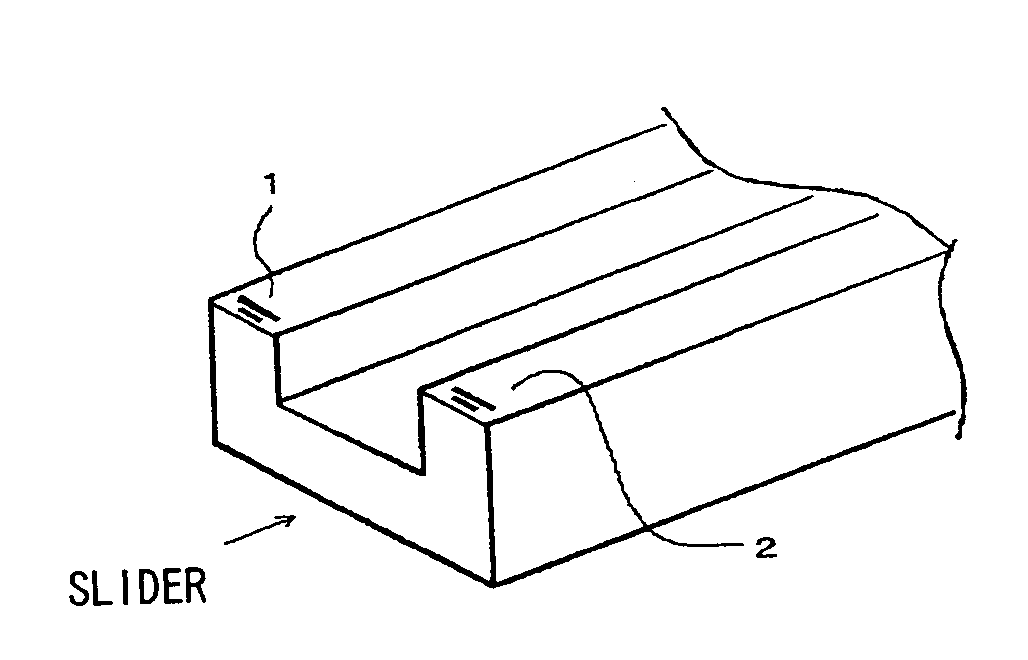
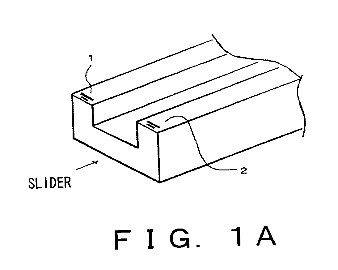
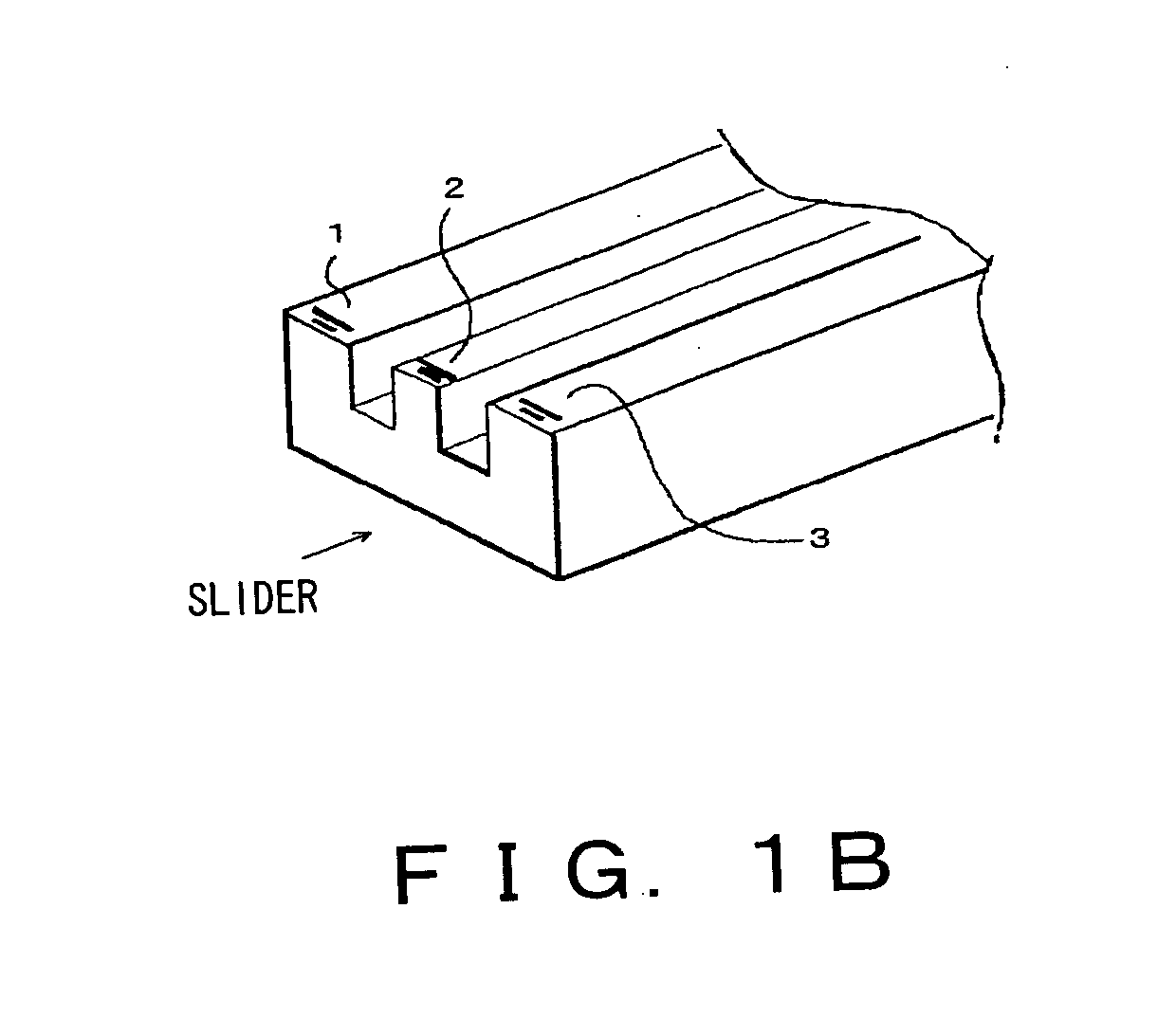
[0069] Each of FIGS. 1A and 1B shows one example of the configuration of a data access head provided in a magnetic disk device according to the present preferred embodiment.

[0070] Each of FIGS. 2A and 2B shows a positional relation of the data access heads on a disk surface, according to the present preferred embodiment.

[0071] A magnetic disk device is provided with a plurality of data access heads (here, magnetic heads) for each arm, according to the present preferred embodiment. FIG. 1A shows one example in which two magnetic heads are provided and FIG. 1B shows one example in which three magnetic heads are provided. The present preferred embodiment is not limited to these configurations and a configuration in which four or more magnetic heads are provided is also applicable.

[0072] In the example of FIG. 1A, magnetic heads (magnetic poles) 1 and 2 are respe...


PUM


Abstract

The present invention aims at offering a magnetic disk device for configuring RAID in a single disk device. The device can configure RAID using one disk and furthermore only one surface (referred to as a single-surface RAID method) neither requiring a plurality of actuators nor performing a data writing processing, etc. more than once. For that purpose, a plurality of data access heads is provided for each arm and the heads are positioned so as to access different tracks on a same surface on a disk.

Description

CROSS REFERENCE TO RELATED APPLICATION [0001] This application is a continuation of international PCT application No. PCT / JP2003 / 001798 filed on Feb. 19, 2003.BACKGROUND OF THE INVENTION [0002] 1. Field of the Invention [0003] The present invention relates to a magnetic disk device configuring RAID (Redundant Arrays of Inexpensive Disks) in a single disk device. [0004] 2. Description of the Related Art [0005] At present, RAID (Redundant Arrays of Inexpensive Disks) is well-known as a method of enhancing the reliability of a magnetic disk. Basically, RAID is a method of redundantly storing data in a plurality of magnetic disks. That is, this method is a storage technology of enhancing both a high-speed processing and the tolerability for a fault by connecting a plurality of disks in parallel and simultaneously controlling all the disks. By adopting RAID, the reduction of data loss at the time of a disk fault, a fault-tolerant system processing at the time of a disk fault, high-speed ...

Claims


Application Information

Patent Timeline
IPC IPC(8): G06F11/00G06F11/10G11B5/012G11B5/48G11B20/10G11B20/12
CPCG06F11/1076G06F11/2069G06F11/2082G06F2211/1092G11B2220/2516G11B5/4886G11B5/4976G11B20/10G11B2005/0002G11B5/012
Inventor NOGUCHI, YASUOTAKE, RIICHIRONISHIKAWA, KATSUHIKOIIDA, ATSUOYOKOHATA, TORU
Owner FUJITSU LTD
Learn More