Float arm assembly and method of manufacture

a technology of float arm and assembly, which is applied in the direction of manufacturing tools, machines/engines, instruments, etc., can solve the problems of affecting the accuracy of the fuel level reading indicated to a user, affecting the performance of the fuel tank, and receiving a potentially misleading value as to the quantity of fuel remaining in the fuel tank. , to achieve the effect of improving the accuracy of the fuel level reading, reducing the potential for variance, and enhancing manufacturing efficiency

Inactive Publication Date: 2005-12-29
WALBRO ENGINE MANAGEMENT
View PDF6 Cites 12 Cited by
  • Summary
  • Abstract
  • Description
  • Claims
  • Application Information

AI Technical Summary

Benefits of technology

[0006] The float arm assembly and method of manufacture therefore provides a float arm assembly that is moveable within a fuel tank in response to a continuously varying fuel level within the fuel tank to provide accurate readings of the fuel level within the fuel tank. With the float being molded to the float arm, the stack up tolerances resulting between the float and the float arm are kept to a minimum, thereby reducing the potential for variances from one float arm assembly to another, and further, improving the accuracy of the fuel level readings. Additionally, the method of construction of the float arm assembly eliminates the need for secondary operations to assemble the float arm to the float, thereby enhancing the manufacturing efficiencies and reducing the costs generally associated with secondary operations, such as labor, capital equipment, floor space and component costs, for example.
[0007] Some of the objects, features and advantages included in at least some of the disclosed embodiments of the invention include providing a float arm assembly for use in a fuel tank that has a reduced number of component parts, provides a float arm assembly facilitating repeatable and reliable fuel level readings, reduces potential stack up tolerance variations in assembly and problems associated therewith in use, minimizes the weight of a float arm assembly, maximizes the buoyancy of a float on a float arm assembly, improves the manufacturing efficiencies for a float arm assembly, maximizes the potential volume for a float on a float arm assembly, allows optimization of the geometry of a float on a float arm assembly, allows optimal design of a float arm to improve the buoyancy of a float attached thereto, is of relatively simple design and provides for a long and useful life in use.

Problems solved by technology

The resulting variances affect the performance of the float arm, and thus, affect the accuracy of the fuel level reading indicated to a user.
As a result, the user receives a potentially misleading value as to the quantity of fuel remaining in the fuel tank.
Additionally, the fasteners used in securing the float to the float arm add additional weight to the assembly, thereby impacting the buoyancy of the float within the fuel, and thus, affecting its performance.
Further, the secondary operations performed in using fasteners to secure the float to the float arm complicate the assembly process, and thus, increase the costs associated with assembling of the float arm assembly.

Method used


Image

  • Float arm assembly and method of manufacture
  • Float arm assembly and method of manufacture
  • Float arm assembly and method of manufacture

Examples


Embodiment Construction

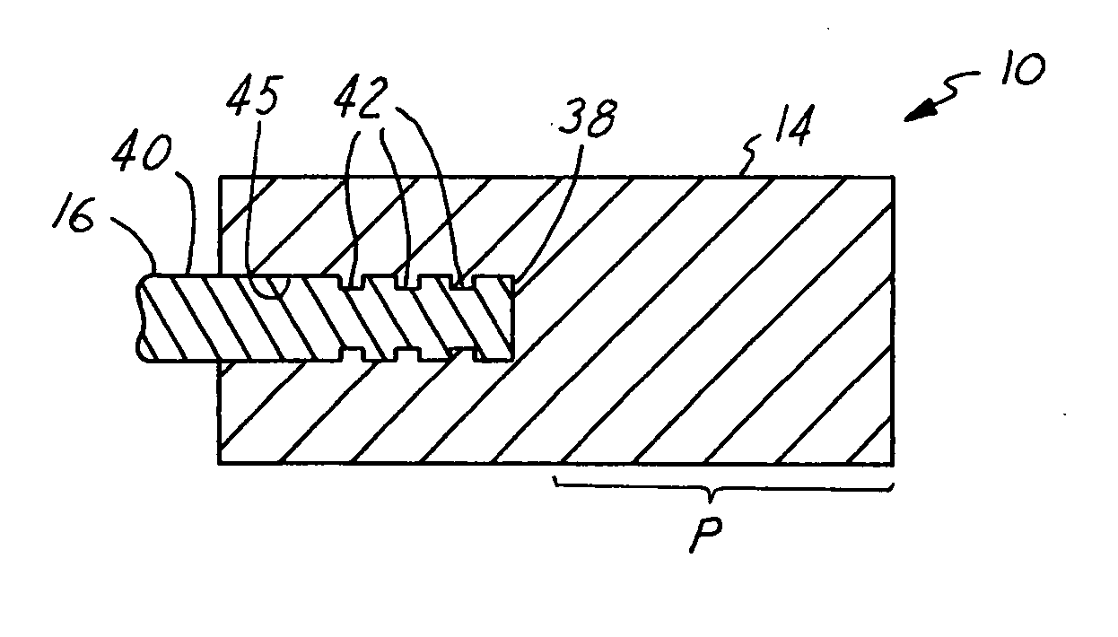
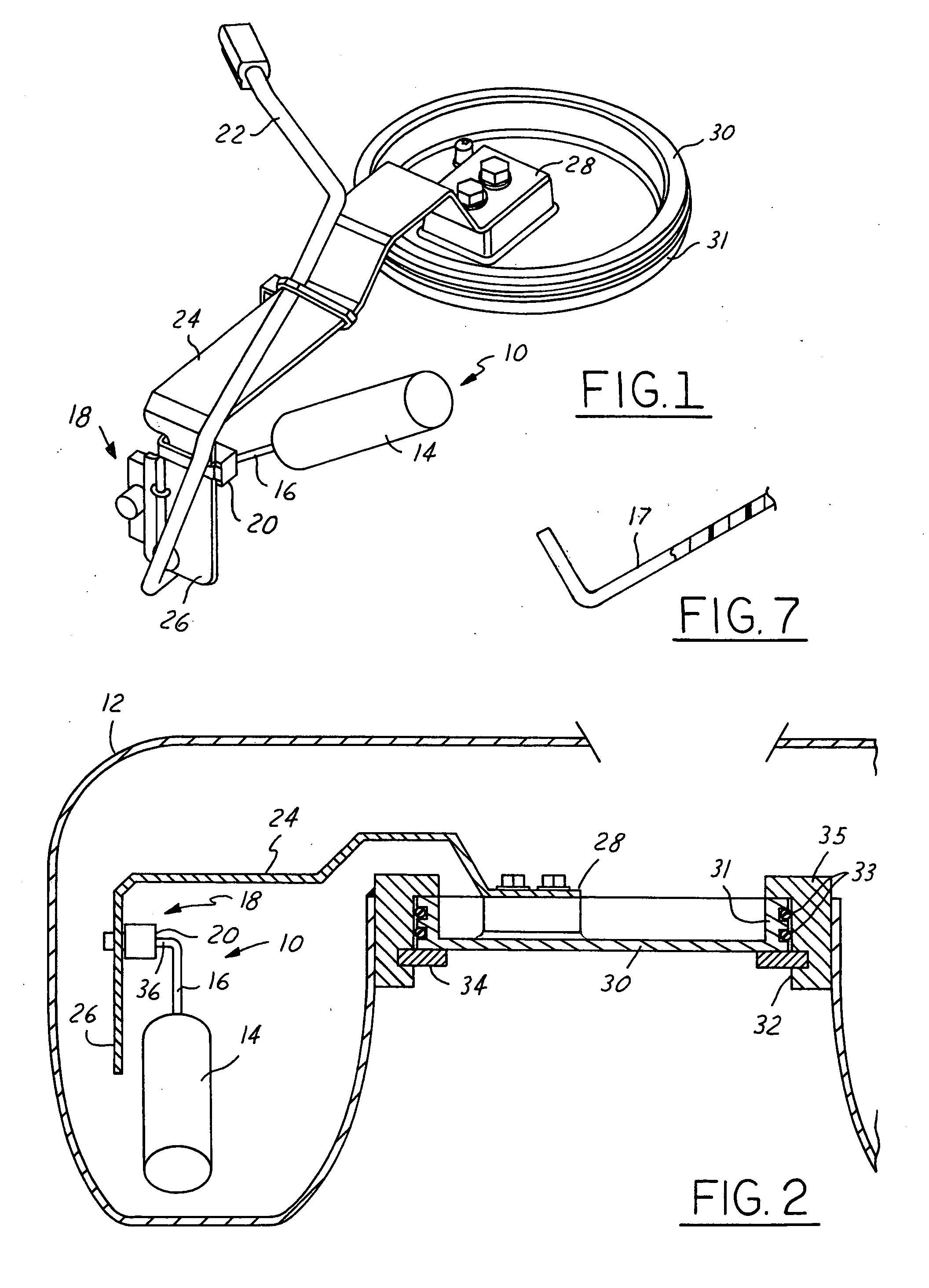
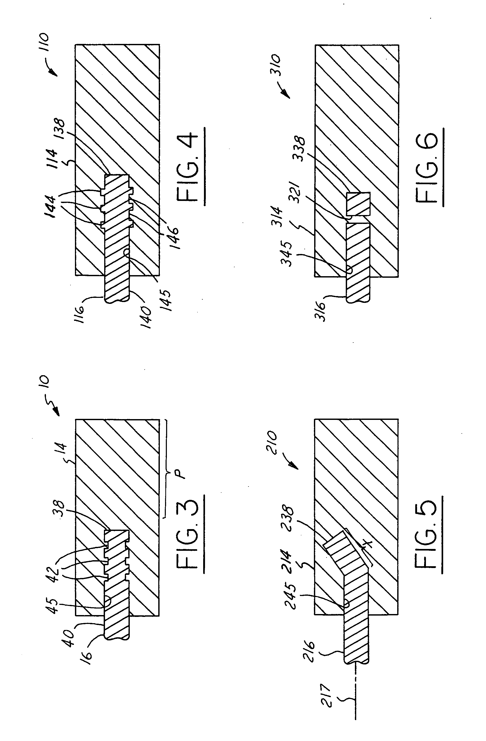
[0016] Referring in more detail to the drawings, FIGS. 1 and 2 illustrate a float arm assembly 10 constructed according to one embodiment of the invention. The float arm assembly 10 is constructed for use within a fuel tank 12 (FIG. 2), such as a fuel tank on a motorcycle, recreational vehicle or an automobile, for example. The assembly 10 has a float 14 molded onto or over at least a portion of a float arm 16, such that the float 14 is carried by the float arm 16 and may be fixed thereto to eliminate or reduce slop or play between the float 14 and the float arm 16. As a result, the float arm assembly 10 is responsive to a change in the fuel level within the fuel tank 12 preferably with little, and more preferably without any relative movement between the float 14 and the float arm 16, thereby facilitating a relatively accurate determination of the level of fuel in the fuel tank.

[0017] The float arm assembly 10 is generally constructed for use as a component of an electromechanical...


PUM

PropertyMeasurementUnit
melt temperatureaaaaaaaaaa

Abstract

A float arm assembly and method of construction therefore has a float arm with a free end and another end arranged for operable communication with a float arm position sensor. A float is molded to the float arm to provide a unitary and rigid float arm assembly.

Description

FIELD OF THE INVENTION [0001] This invention relates generally to fuel systems and more particularly to fuel level senders for use in a fuel tank. BACKGROUND OF THE INVENTION [0002] Vehicles having internal combustion engines typically have fuel tanks for maintaining liquid fuel therein. Generally, the fuel tank has a fuel level sender therein to provide an indication to a user, such as on a fuel level gauge, as to the amount of fuel within the tank. Commonly, the fuel level sender incorporates a float arm assembly having a float arm extending through a float to facilitate attaching the float on the float arm. Further, it is known to use at least one or more washers received adjacent opposite ends of the float in combination with a fastener, such as a self locking Tinnerman® style washer or threaded nut to maintain the float fastened to the float arm. [0003] By securing a float to a float arm through the use of fasteners, typically performed in a secondary operation, variances resul...

Claims


Application Information

Patent Timeline
Patent Type & Authority Applications(United States)
IPC IPC(8): B29C39/10B29C45/14B29C45/16B29C49/20G01F23/32G01F23/36G01F23/76
CPCB29C45/14311B29C45/1657G01F23/76G01F23/36B29L2031/7172
Inventor COTTON, KENNETH J.KALLIO, DANIEL H.PARROTT, RICHARD J. II
Owner WALBRO ENGINE MANAGEMENT
Why Eureka
Try Eureka