Printing press

a printing press and press body technology, applied in printing presses, office printing, printing, etc., can solve the problems of inability to mount the printing plate on the plate cylinder, inability to bring the cutouts, and inability to control the drive of the pressing gripper

Inactive Publication Date: 2005-12-29
RYOBI
View PDF2 Cites 0 Cited by
  • Summary
  • Abstract
  • Description
  • Claims
  • Application Information

AI Technical Summary

Benefits of technology

[0012] With this arrangement, the sucker is prevented from being moved in a direction parallel to the axis of the plate cylinder at a position, at which the sucker starts holding the printing plate by suction, and therefore is held in stationary position. Thus, it is possible to securely hold the printing plate by suction. Also, the sucker is rele...

Problems solved by technology

If the printing plate on the printing plate guide plate is axially displaced relative to a give position, the engaged means of the printing plate is unlikely to be in alignment with the engaging means so that, with the printing press of this type, which automatically drives the clamping gripper, a signal generated upon the alignment of a printing plate with the plate cylinder is not output, and hence the clamping gripper cannot be controlledly driven.
This makes it impossible to mount the printing plate on the plate cylinder.
The returning of a plate registration (the axial position) of the plate cylinder to the original point (position) is required for the reason that if the plate registration (the axial position) of the plate cylinder has been displaced from a proper position after the use of the printing plate for the last printing operation, a newly supplied printing plate for the subsequent...

Method used


Image

  • Printing press
  • Printing press
  • Printing press

Examples


Embodiment Construction

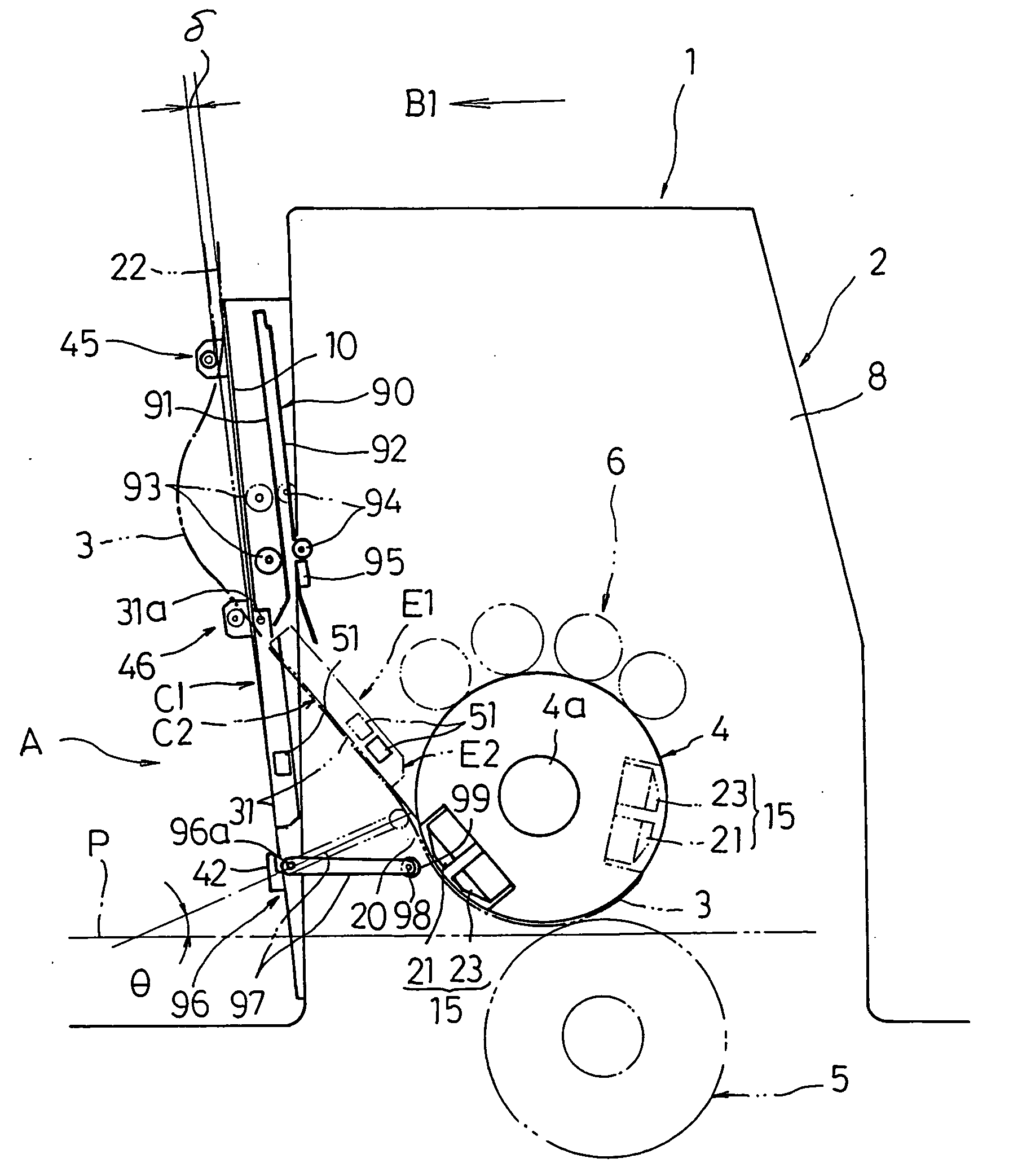
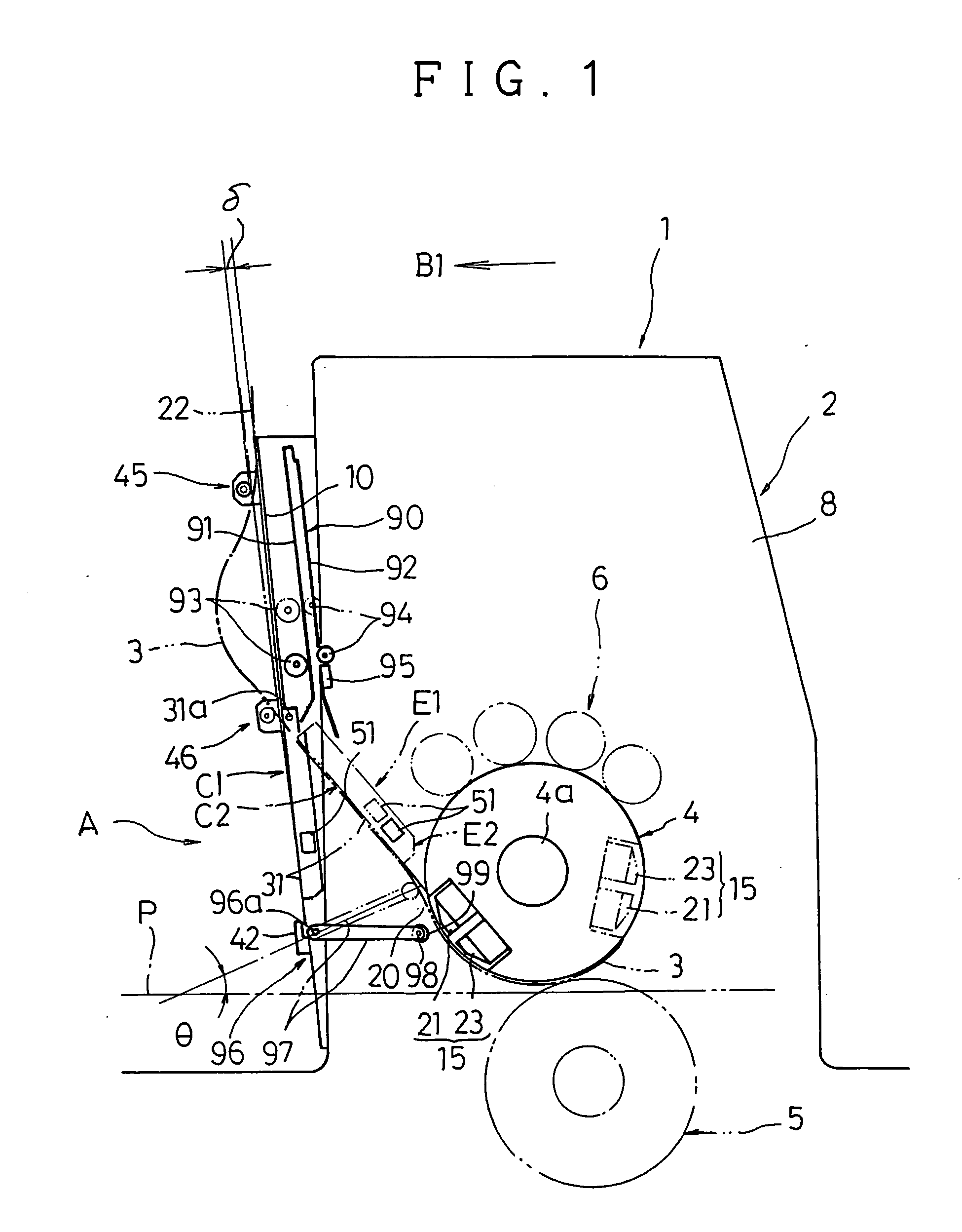
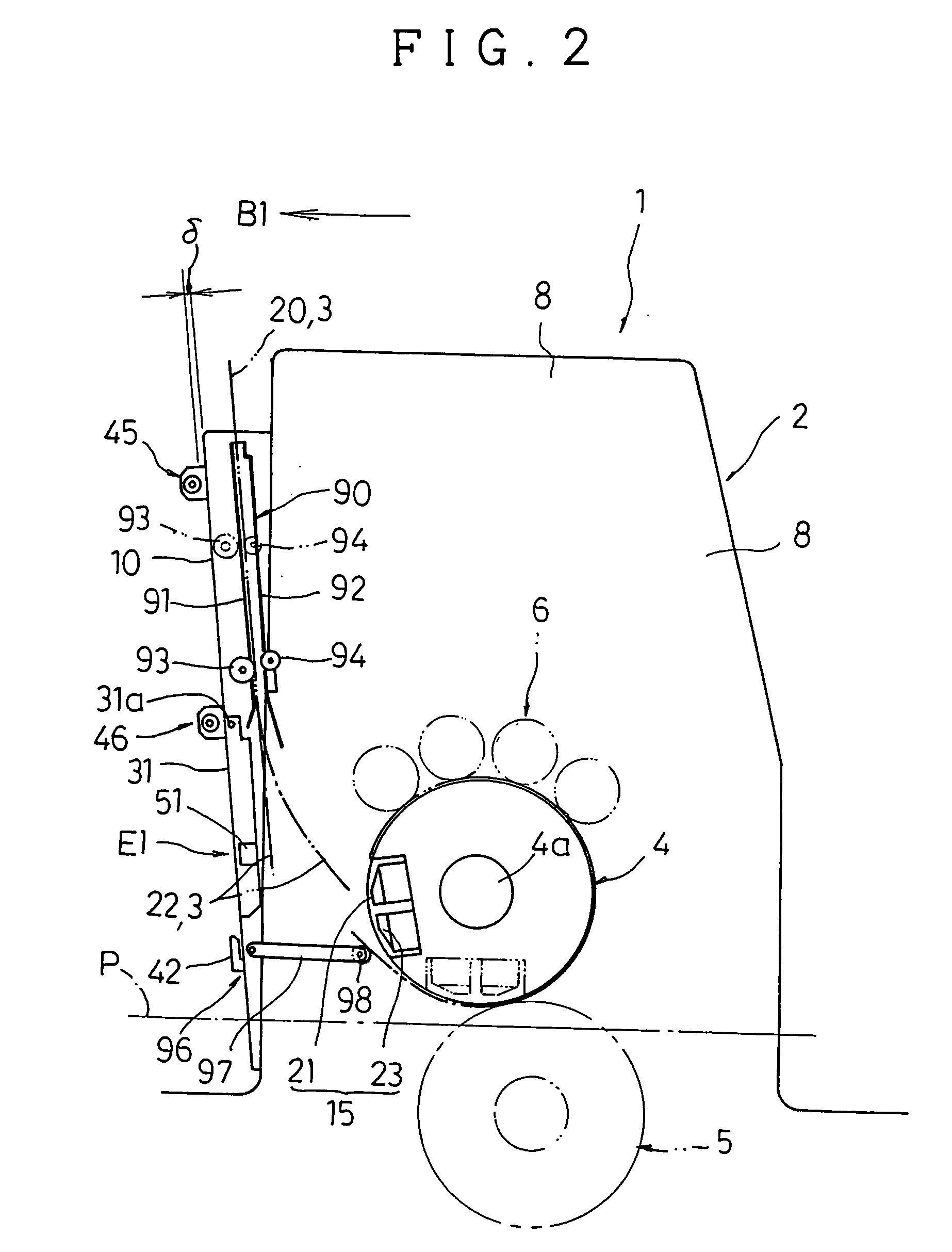
[0026] Now, the description will be made for an embodiment of a printing press by taking for example a sheet-fed printing press with reference to the drawings attached hereto. FIGS. 1 and 2 are schematic lateral cross sectional views of a printing section of a sheet-fed printing press. FIG. 3 is a rear view of a printing plate guide plate illustrating the structure of a plate supply device. FIG. 4 is a front view of a downstream sided front plate. FIG. 5 is a lateral cross sectional view illustrating the structure of the plate supply device. FIG. 6 is an enlarged view of a partly broken-out section of FIG. 3.

[0027] Generally, a sheet-fed printing press has a sheet feeding section on the upstream side, a sheet discharge section on the downstream side and a printing section (also called as a printing unit) therebetween. All the Figures attached hereto illustrate the structure of a printing section 1. In this embodiment, only the single printing section 1 is illustrated for ease of ex...


PUM


Abstract

A printing press can securely supply a printing plate while bringing a printing plate into alignment with a plate cylinder in an axial direction of the plate cylinder, as well as omitting the necessity to return the plate registration of the plate cylinder to the original point. The printing press includes a printing plate guide plate that is pivotally movably mounted in an opening of a body cover that covers the plate cylinder, a sucker for holding a printing plate by suction so as to pull the same towards the printing plate guide plate. The sucker is disposed so as to be movable towards a clamping gripper disposed on the plate cylinder and in a direction parallel to an axis of the plate cylinder.

Description

CROSS REFERENCE TO RELATED APPLICATION [0001] This application claims priority from Japanese Patent Application No. 2004-188023, which is incorporated herein by reference. BACKGROUND OF THE INVENTION [0002] 1. Field of the Invention [0003] The present invention relates to a printing press and more particularly a structure of a printing section disposed between a sheet feeding section and a sheet discharge section so as to supply a printing plate to a clamping gripper that is disposed on a plate cylinder and to mount the supplied printing plate on the plate cylinder. [0004] 2. Related Art [0005] A sheet-fed printing press (hereinafter referred simply to a printing press) generally includes a printing section between a sheet feeding section and a sheet discharge section. This printing section is to print on sheets by a printing plate mounted on a plate cylinder. There is a necessity to mount a printing plate on the plate cylinder with accurate alignment. For mounting a printing plate ...

Claims


Application Information

Patent Timeline
IPC IPC(8): B41F1/28B41F13/10B41F27/12
CPCB41F27/1206
Inventor FUJIWARA, SHIGEO
Owner RYOBI
Why Eureka
Try Eureka