Livestock facility equipment network

a technology for livestock facilities and equipment networks, applied in the field of expanding livestock facility equipment networks, can solve the problems of unfavorable operation of the system, inability to provide immediate notification of an alarm condition to the operator, and uneven feed distribution within the feed delivery system

Inactive Publication Date: 2005-12-29
BECS TECH
View PDF36 Cites 25 Cited by
  • Summary
  • Abstract
  • Description
  • Claims
  • Application Information

AI Technical Summary

Benefits of technology

[0010] Briefly stated, a preferred embodiment of the present invention provides a livestock facility equipment network over which data is received from two or more automated pieces of equipment or equipment monitors, and utilized by a control unit to provide an overall indication of the status of the livestock facility, including feed supply management, animal health conditions, and equipment operational conditions.

Problems solved by technology

However, these systems suffer several drawbacks.
Feed may be unevenly distributed within the feed delivery system, blocked from movement, or completely absent.
Traditionally, these automated pieces of equipment or monitors are operated in isolation and do not coordinate the acquired information available across multiple units, or between different types of equipment or monitors.
However, currently available systems do not provide immediate notification of an alarm condition to an operator without initially awaiting for the predetermined excess period of time.
Furthermore, currently available systems do not provide detailed diagnostic information regarding the specific nature or source of the alarm condition in animal feed systems.
Hence, diagnosis of potentially serious problems in equipment operation and animal health may be missed or delayed.
In a feed delivery system which utilizes only activation of a feed delivery auger motor, failure to dispense feed from a storage silo will not be detected, but auger motor activation will be, providing the false impression that a quantity of feed was delivered to a feeding station.
However, the conventional system can not provide an indication if the slide gate at the grain silo was open or closed, if there was no feed present in the grain silo, or if a feed bridge condition has occurred within the feed system, blocking feed from being delivered to the feed troughs.

Method used


Image

  • Livestock facility equipment network
  • Livestock facility equipment network
  • Livestock facility equipment network

Examples


Embodiment Construction

[0019] The following detailed description illustrates the invention by way of example and not by way of limitation. The description clearly enables one skilled in the art to make and use the invention, describes several embodiments, adaptations, variations, alternatives, and uses of the invention, including what is presently believed to be the best mode of carrying out the invention.

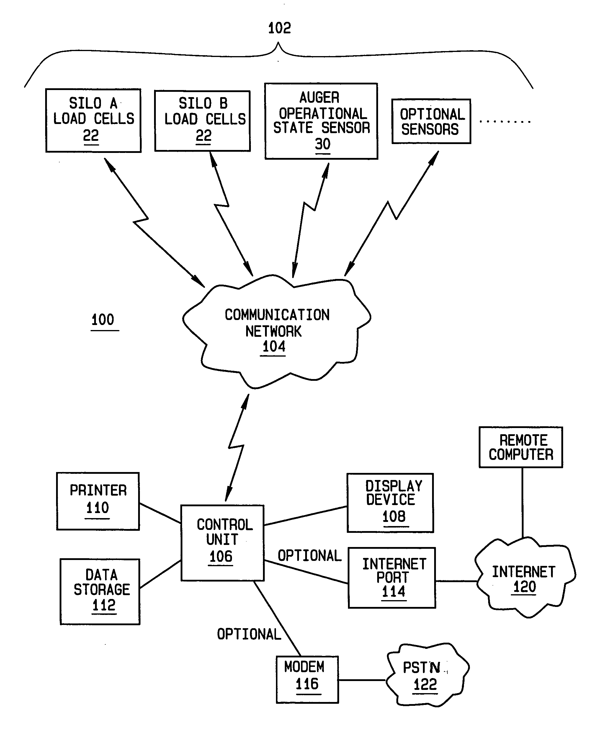
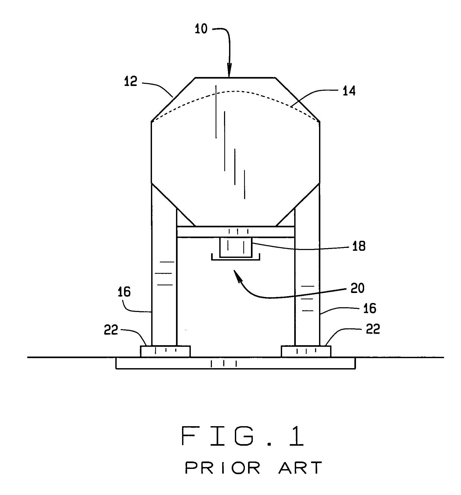
[0020] Turning to FIG. 1, a conventional grain silo is shown at 10, having a housing 12 within which is stored a quantity of grain or bulk feed 14. The housing 12 is typically supported by a set of legs 16, elevating the housing 12 above ground, such that bulk feed 14 may be gravity dispensed from a hopper 18 at the base of the housing 12, having a slide gate opening 20. A set of load sensors 22 are associated with the legs 16 of the grain silo 10, and provide signals indicative of the load carried by each leg 16.

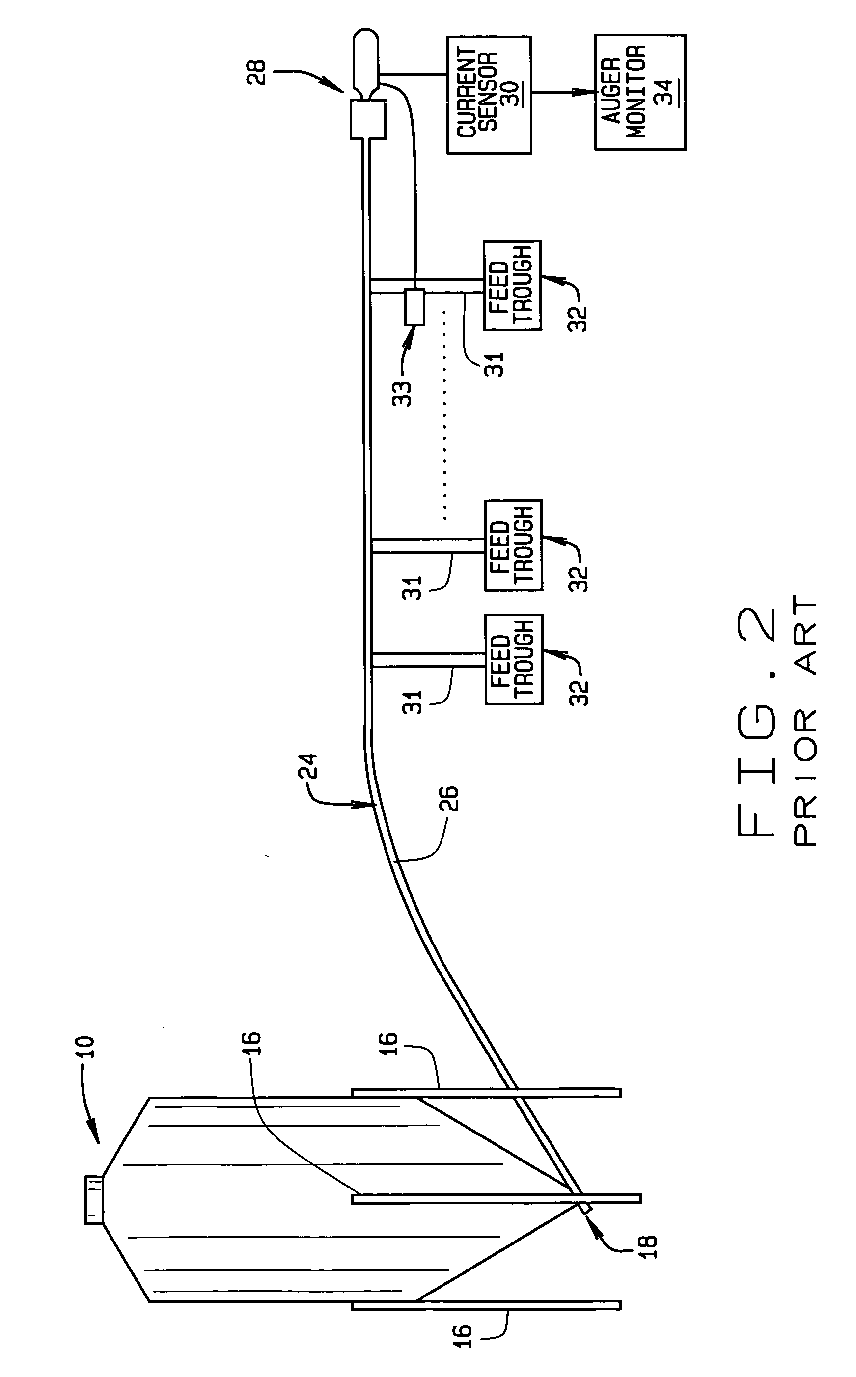
[0021] As shown in FIG. 2, the hopper 18 of the grain silo 10 is commonly coupled to a fee...


PUM


Abstract

An expandable livestock facility equipment network over which data is received from various automated pieces of equipment or monitors, and utilized by a control unit to provide an overall indication of the status of the livestock facility, including feed supply management, animal health conditions, and equipment operational conditions.

Description

CROSS-REFERENCE TO RELATED APPLICATIONS [0001] Not Applicable. STATEMENT REGARDING FEDERALLY SPONSORED RESEARCH [0002] Not Applicable. BACKGROUND OF THE INVENTION [0003] The present invention is related to a livestock facility consumables tracking system, and in particular, to an expandable livestock facility equipment network adapted to track inventory and usage of feed supplies, the operational status of feeding equipment, and the health of livestock in an automated livestock facility using a network of interconnected sensors. [0004] Modern farms often utilize automation in the monitoring and delivery of feed and water to livestock. Examples of farm and livestock automation include the use of water meters to document the delivery or consumption of water by a group of animals, automatic feeders that deliver controlled quantities of feed to feeding stations at predetermined times of day, regulating the feed available to the animals, and inventory measurement systems (e.g., grain bin...

Claims


Application Information

Patent Timeline
Patent Type & Authority Applications(United States)
IPC IPC(8): A01K5/02A01K29/00
CPCA01K5/02A01K29/00A01K5/0283G01G19/414
Inventor BELL, TIMOTHY L.CHAMBERLAIN, ROGER D.
Owner BECS TECH
Why Eureka
Try Eureka