
Cylinder operation control apparatus for internal combustion engine

a technology of operation control and internal combustion engine, which is applied in the direction of valve arrangement, machine/engine, output power, etc., can solve the problem of not greatly improving fuel economy, and achieve the effect of preferable operation efficiency

Inactive Publication Date: 2005-12-29
HONDA MOTOR CO LTD
View PDF3 Cites 19 Cited by
  • Summary
  • Abstract
  • Description
  • Claims
  • Application Information

AI Technical Summary

Benefits of technology

[0007] In view of the above circumstances, an object of the present invention is to provide a cylinder operation control apparatus for an internal combustion engine, which enables maximal improvement in fuel economy due to a cylinder deactivation operation, while also enabling drive of the vehicle even when a valve lift operating device in a cylinder deactivation mechanism fails.
[0009] According to the above cylinder operation control apparatus of the present invention, the internal combustion engine can be placed in the all-cylinder activation mode or in the cylinder deactivation mode by operating the lift amount changing device using the lift operating device so as to control the amount of lifts of the intake and exhaust valves. In addition, the internal combustion engine can be enforcedly returned to the all-cylinder activation mode from the cylinder deactivation mode by operating the cylinder activation enforcing device; therefore, the internal combustion engine can be reliably returned to the all-cylinder activation mode from a state in which all of the cylinders are deactivated.
[0011] According to the above cylinder operation control apparatus of the present invention, by suspending the operations of the intake and exhaust valves using the hydraulic variable valve timing mechanism, the engine friction can be further reduced, and fuel economy can also be further improved.
[0014] According to the above cylinder operation control apparatus of the present invention, the operation mode of the internal combustion engine can be switched between the all-cylinder activation mode and the cylinder deactivation mode by optionally supplying the operation oil from the hydraulic power source to the cylinder activation passage or to the cylinder deactivation passage using the switching device. Moreover, the operation oil can be supplied to the cylinder activation passage so as to place the engine in the all-cylinder activation mode by connecting the oil supply branching passage to the cylinder activation passage using the cylinder activation port of the cylinder activation enforcing device and by connecting the drain branching passage to the cylinder deactivation passage using the cylinder deactivation port even when the engine is supposed to be placed in the cylinder deactivation mode in which the operation oil is supplied to the cylinder deactivation passage by the operation of the switching device. Therefore, the internal combustion engine can be reliably returned to the all-cylinder activation mode from a state in which all of the cylinders are deactivated.
[0016] According to the above cylinder operation control apparatus of the present invention, the connection or disconnection between the supply branching passage and the cylinder activation passage, and the connection or disconnection between the drain branching passage and the cylinder deactivation passage can be performed by the cylinder activation port and the cylinder deactivation port, i.e., the connection or disconnection between the supply branching passage and the cylinder activation passage, and the connection or disconnection between the drain branching passage and the cylinder deactivation passage can be executed by just a single operation of the spool; therefore, a preferable efficiency in operation can be obtained.

Problems solved by technology

Accordingly, friction due to the normally activated cylinders remain unchanged during a deceleration operation; therefore, fuel economy is not greatly improved.

Method used


Image

  • Cylinder operation control apparatus for internal combustion engine
  • Cylinder operation control apparatus for internal combustion engine
  • Cylinder operation control apparatus for internal combustion engine

Examples


Embodiment Construction

[0026] The preferred embodiments of the present invention will be explained below with reference to the appended drawings.

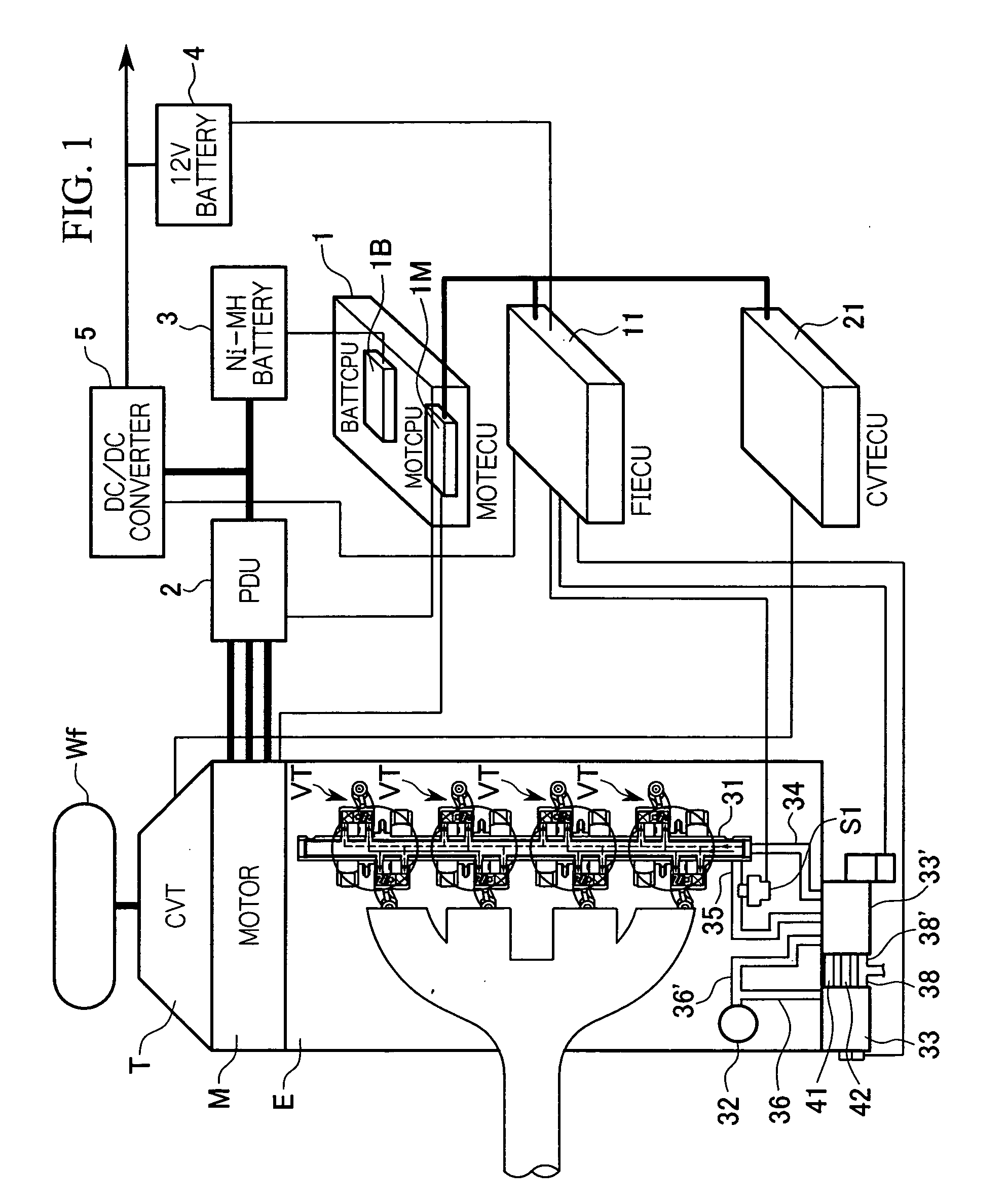
[0027] The construction of a parallel hybrid vehicle, which includes a hydraulic pressure supplying device for valve trains according to a first embodiment of the present invention, will be explained below with reference to FIG. 1.

[0028] As shown in FIG. 1, the hybrid vehicle includes an engine E, a motor M, and a transmission T, which are coupled to each other in series. The driving power generated by at least one of the engine E and the motor M is transmitted via, for example, a CVT (continuously variable transmission) as the transmission T (the transmission T may be a manual transmission) to front wheels Wf as driving wheels. When the driving power is transmitted from the driving wheels Wf to the motor M during deceleration of the hybrid vehicle, the motor M acts as a generator for applying a so-called regenerative braking force to the vehicle, i.e., the kin...


PUM


Abstract

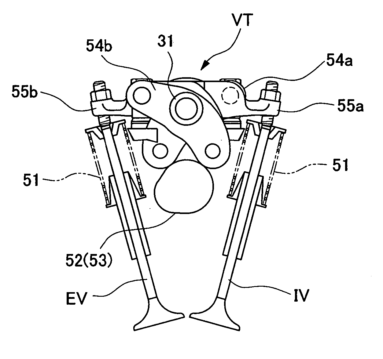
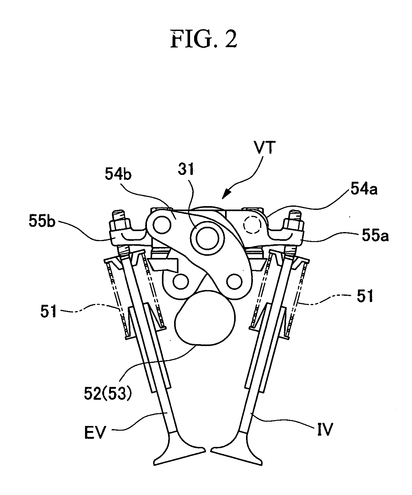
A cylinder operation control apparatus includes: an internal combustion engine (E) which is adapted to operate in an all-cylinder activation mode and in a cylinder deactivation mode; a lift amount changing device (VT) which is associated with the internal combustion engine (E), and which enables switching between the all-cylinder activation mode and the cylinder deactivation mode by changing the amount of lifts of intake and exhaust valves (IV, EV) associated with the cylinders; a lift operating device (33) which is associated with the lift amount changing device (VT) to operate the same; a cylinder activation enforcing device (33′) which is operatively disposed between the lift amount changing device (VT) and the lift operating device (33) so as to enforce the all-cylinder activation mode as necessary.

Description

BACKGROUND OF THE INVENTION [0001] 1. Field of the Invention [0002] The present invention relates to a cylinder operation control apparatus for an internal combustion engine, which enables a switching operation between an all-cylinder activation mode in which all cylinders of the engine are activated, and a cylinder deactivation mode in which at least a cylinder of the engine is deactivated. [0003] 2. Description of the Related Art [0004] Among hybrid vehicles, a type of hybrid vehicle is known in which a cylinder deactivation operation is executed, for example, by controlling valve trains of the engine using hydraulic control method in order to further improve fuel economy by means of reduction in friction of the engine. In this type of hybrid vehicle, when the vehicle enters a deceleration state, a cylinder deactivation operation is executed along with a fuel cut operation so as to decrease engine friction, and as a result, the amount of regenerated electric energy is increased by...

Claims


Application Information

Patent Timeline
Patent Type & Authority Applications(United States)
IPC IPC(8): F01L1/26F01L13/00F02D13/02F02D13/06
CPCF01L1/267F01L2105/00F01L13/0036F01L13/0005F01L2305/00
Inventor HASEBE, TETSUYAKURODA, SHIGETAKASUGIYAMA, TETSU
Owner HONDA MOTOR CO LTD
Learn More