Heat exchanger

a heat exchanger and heat exchanger technology, applied in indirect heat exchangers, lighting and heating apparatus, stationary conduit assemblies, etc., can solve the problems of uniform air temperature flowing from the refrigerant evaporator, deterioration of refrigerant distribution performance, and increase of pressure loss in the refrigerant evaporator, so as to improve the heat exchange performance between the first and second mediums, improve the distribution of mediums into tubes, and improve the effect of heat exchange performan

Inactive Publication Date: 2005-12-29
DENSO CORP
View PDF17 Cites 45 Cited by
  • Summary
  • Abstract
  • Description
  • Claims
  • Application Information

AI Technical Summary

Benefits of technology

[0007] It is another object of the present invention to provide a heat exchanger in which the same tank member can be used even when a core length in a tube longitudinal direction is changed.
[0008] It is further another object of the present invention to provide a refrigerant evaporator used as a heat exchanger, which can effectively improve refrigerant distribution in tubes.
[0017] Preferably, the third plate member has space holes for forming the second distribution passage at positions corresponding to the tubes in the tank longitudinal direction, and areas of the space holes are set to be gradually larger from an end portion adjacent to a refrigerant inlet to the other end portion in the tank longitudinal direction. In this case, the refrigerant distribution in the tubes in the tube laminating direction can be further improved.
[0019] Furthermore, the downstream tank portion includes a partition portion for partitioning the first joining passage and the second joining passage, and the partition portion has communication holes through which the first joining passage communicates with the second joining passage. In addition, the communication holes are provided in the partition portion to prevent a bias flow of the first medium in the tubes. Therefore, the refrigerant distribution performance can be further improved. For example, the communication holes are set such that a total area of the communication holes is larger than a total passage sectional area of the tubes. The downstream tank portion may be integrated with the upstream tank portion at one end side of the core portion.
[0021] In the heat exchanger, a medium turning tank portion is disposed to have a joining space for joining the first medium after passing through the first passing portion, a distribution space for distribution the first medium from the joining space into the second passing portion, and a pair of first and second communication portions through which the joining space communicates with the distribution space. Furthermore, the first and second communication portions extend in a tank longitudinal direction, the joining space is divided into first and second joining space parts in a tank longitudinal direction, the distribution space is divided into first and second distribution space parts in the tank longitudinal direction at positions corresponding the first and second joining space parts, respectively, the first joining space part communicates with the second distribution space part through the first communication portion, and the second joining space part communicates with the first distribution space part through the second communication portion. Accordingly, the flow of the first medium can be turned in cross in the medium turning tank portion, and medium distribution into the tubes can be improved with a simple structure.
[0022] Even in this case, the upstream tank portion can be provided with a first distribution passage for distributing the first medium in the tank longitudinal direction so as to distribute the first medium into the tubes laminated in a direction parallel to the tank longitudinal direction, a second distribution passage for distributing the first medium from the first distribution passage into the tubes in a tank width direction that is perpendicular to both the tube longitudinal direction and the tank longitudinal direction, and a communication passage through which the first medium from the first distribution passage is supplied to the second distribution passage after flowing in the tank longitudinal direction. Accordingly, heat exchanging performance between the first and second mediums can be further improved.

Problems solved by technology

For example, when a tank sectional area and a tube thickness dimension are reduced, a pressure loss is increased in the refrigerant evaporator.
Therefore, a refrigerant distribution performance is deteriorated, and an air temperature flowing from the refrigerant evaporator becomes ununiform.
However, in this case, a piping structure for introducing the refrigerant to the refrigerant inlets becomes complex, and a dead space becomes larger.
Therefore, manufacturing steps become complex.
In contrast, in a whole-pass type refrigerant evaporator (one pass type), it is difficult to improve a refrigerant distribution performance with a simple structure.

Method used


Image

  • Heat exchanger
  • Heat exchanger
  • Heat exchanger

Examples


first embodiment

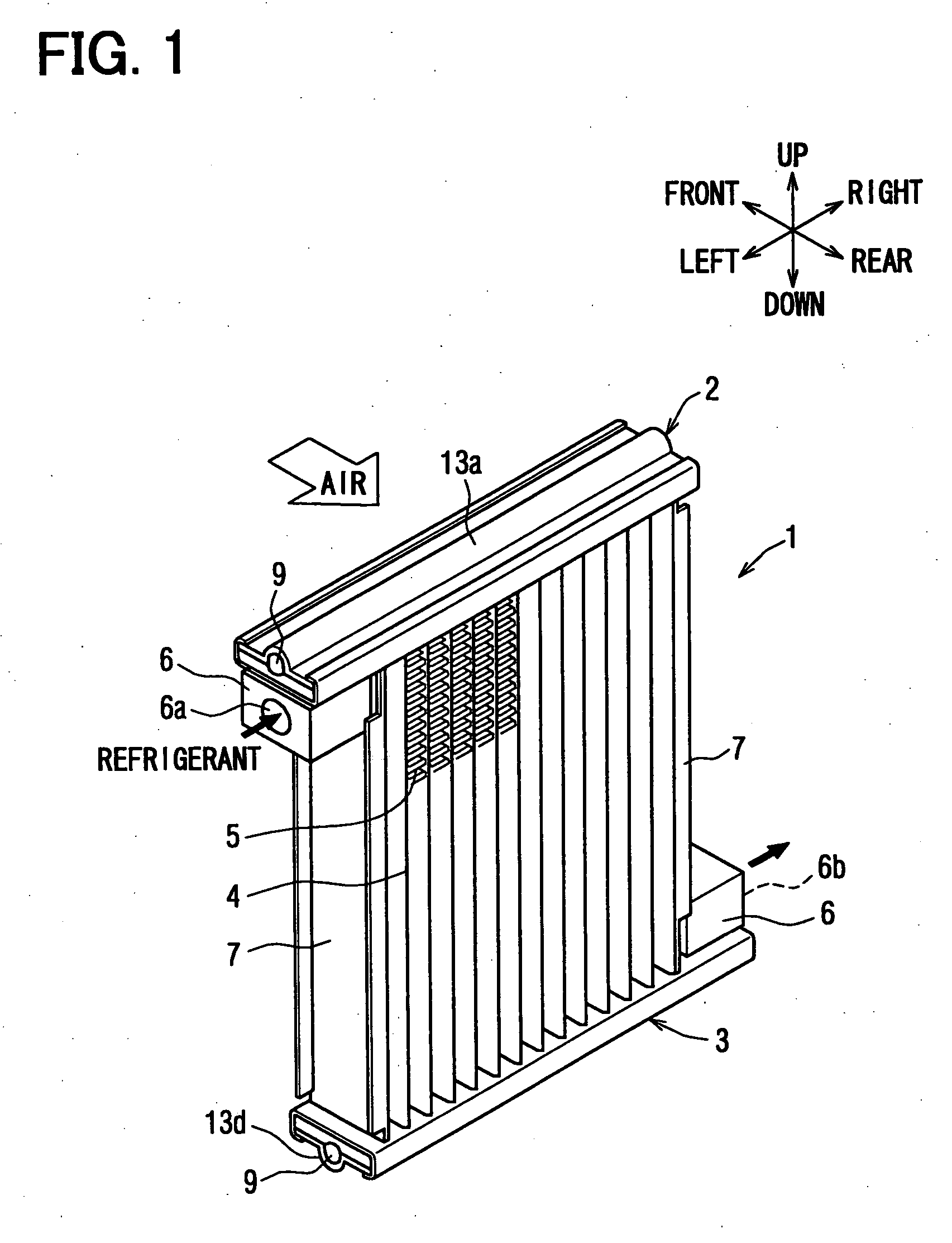
[0040] In this embodiment, a heat exchanger of the present invention is typically used as a refrigerant evaporator. FIG. 1 shows a refrigerant evaporator 1 of the first embodiment, in a state where the refrigerant evaporator 1 is actually used in a refrigerant cycle system. In this example shown in FIG. 1, the refrigerant evaporator 1 is arranged as shown in FIG. 1, in the front-rear direction, the right-left direction and the up-down direction (vertical direction). Here, the front-rear direction corresponds to a tank width direction, the right-left direction corresponds to a tank longitudinal direction, and the up-down direction corresponds to a tube longitudinal direction. However, the using arrangement of the refrigerant evaporator 1 can be suitably changed.

[0041] The refrigerant evaporator 1 can be suitably used for a super-critical refrigerant cycle using CO2, for example. In the super-critical refrigerant cycle, the pressure of high-pressure side refrigerant becomes equal to ...

second embodiment

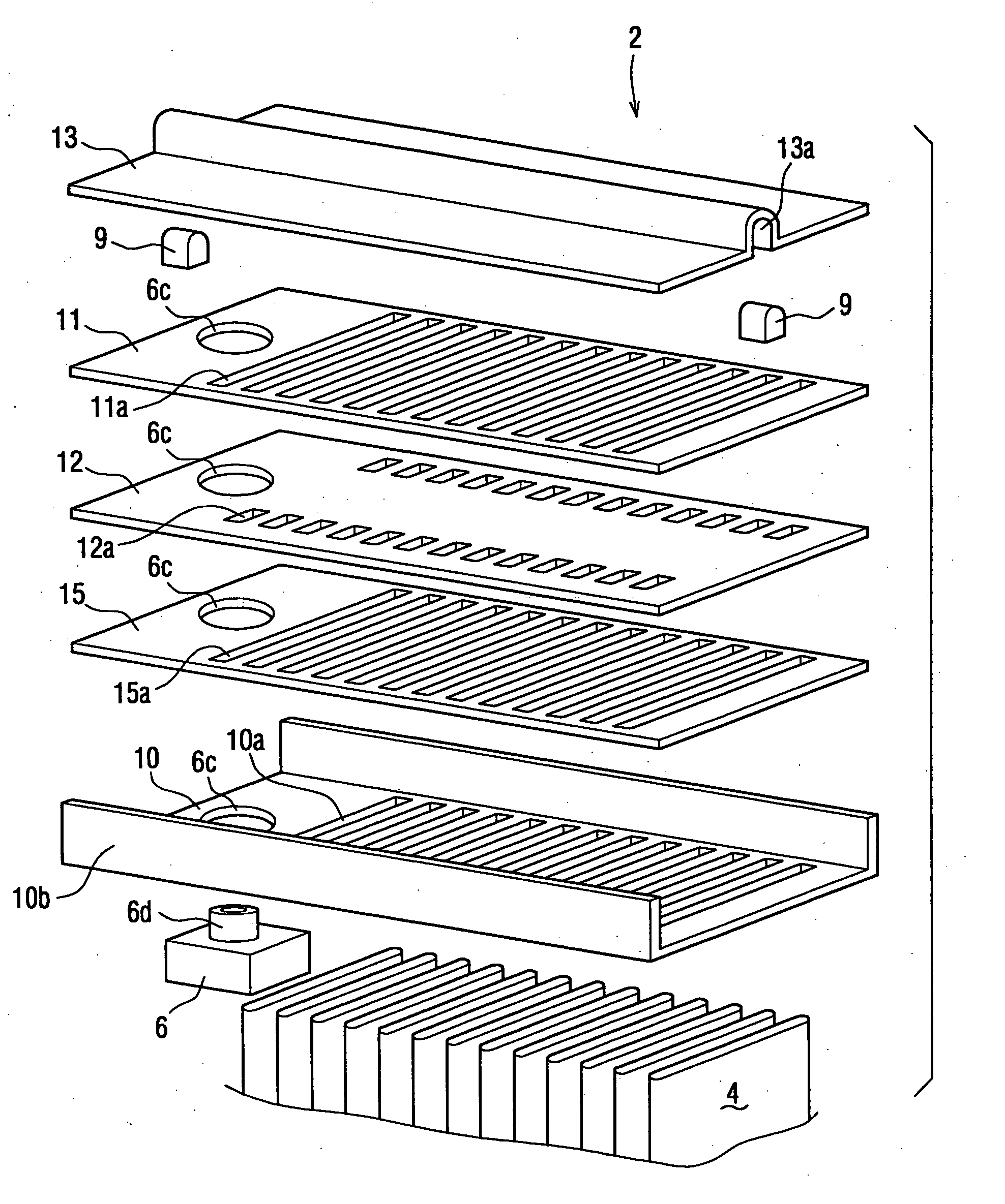
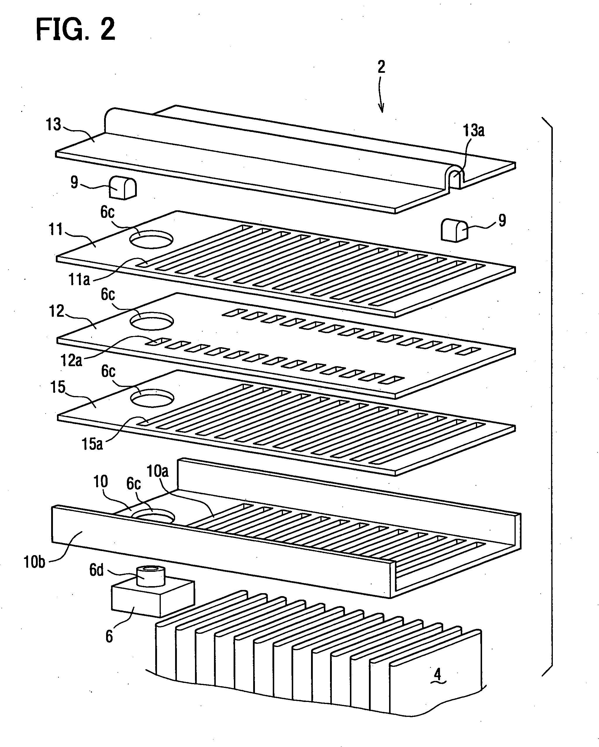
[0070]FIG. 8A is a perspective view showing a refrigerant evaporator 1 according to the second embodiment, and FIG. 8B is an enlarged perspective view showing a part of a core portion of the refrigerant evaporator 1 in FIG. 8B. In the above-described first embodiment, refrigerant flows in one way in the tube longitudinal direction through all the tubes 4 of the core portion without being U-turned. However, in the second embodiment, the tubes 4 are arranged in two lines in a flow direction of the second medium (e.g., air) so that refrigerant flows through all the tubes 4 on one line and flows through all the tubes 4 on the other line after being U-turned.

[0071] In the second embodiment, the refrigerant evaporator 1 includes an upper tank portion 2, 3, a refrigerant turning portion T and the core portion between the upper tank portion 2, 3 and the refrigerant turning portion T. The upper tank portion 2, 3 includes an upstream tank portion 2 and a downstream tank portion 3. The upstre...

third embodiment

[0092]FIG. 13 is a perspective view showing a refrigerant evaporator 1 according to the third embodiment, and FIG. 14 is a disassembled perspective view showing a refrigerant turning portion T of the refrigerant evaporator 1 in FIG. 13. The refrigerant evaporator 1 shown in FIG. 13 is generally used in a position indicated by arrows in the up-down direction, the right-left direction and the front-rear direction. For example, a refrigerant turning portion T in FIG. 13 is used as the bottom of the evaporator 1, and upstream and downstream tank portions 2, 3 in FIG. 13 are used as the top of the refrigerant evaporator 1.

[0093] In this embodiment, the structures of the upstream and downstream tank portions 2, 3 are similar to those of the above-described second embodiment. The refrigerant turning portion T is formed by stacking a header plate 14, a first space forming plate 15, a crossing plate 16, a second space forming plate 15′ and a tank header plate 17, on a temporarily assembled ...


PUM


Abstract

A refrigerant evaporator includes an upstream tank portion for distributing refrigerant into all laminated tubes of a core portion. The upstream tank portion includes a first distribution passage for distributing the refrigerant into the tubes in a direction parallel to a tank longitudinal direction, a second distribution passage for distributing the refrigerant from the first distribution passage into the tubes in a tank width direction, and a communication passage through which the refrigerant from the first distribution passage is supplied to the second distribution passage after flowing in the tank longitudinal direction. Therefore, refrigerant can be uniformly introduced into all the tubes.

Description

CROSS REFERENCE TO RELATED APPLICATION [0001] This application is based on Japanese Patent Application No. 2004-190101 filed on Jun. 28, 2004, the contents of which are incorporated herein by reference in its entirety. FIELD OF THE INVENTION [0002] The present invention relates to a heat exchanger for performing heat exchange between first and second mediums. The heat exchanger can be suitably used for a refrigerant evaporator in which refrigerant of a refrigerant cycle system is evaporated. BACKGROUND OF THE INVENTION [0003] As a refrigerant evaporator, a multi-flow type heat exchanger is described in U.S. Pat. No. 6,339,937 (JP 2001-324290A) or a serpentine-type heat exchanger is described in JP 2001-12821A, for example. In this case, when a core width dimension of an evaporator is reduced in order to reduce the size or the weight of the evaporator, a refrigerant passage sectional area is reduced. For example, when a tank sectional area and a tube thickness dimension are reduced, ...

Claims


Application Information

Patent Timeline
Patent Type & Authority Applications(United States)
IPC IPC(8): F28D1/053F28F9/02F28F27/02
CPCF28D1/05391F28D2021/0085F28F9/0278F28F9/0221F28F9/0204
Inventor KATOH, YOSHIKIKAWAKUBO, MASAAKIHASEGAWA, ETSUO
Owner DENSO CORP
Why Eureka
Try Eureka