
Brush assemblies

a technology of brush assemblies and components, applied in the direction of current collectors, structural associations, dynamo-electric machines, etc., can solve the problems of insufficient rfi suppression performance of components, difficult effect of mounting, and inability to mount components in this manner

Inactive Publication Date: 2005-12-29
ENERGY CONVERSION SYST HLDG
View PDF13 Cites 17 Cited by
  • Summary
  • Abstract
  • Description
  • Claims
  • Application Information

AI Technical Summary

Benefits of technology

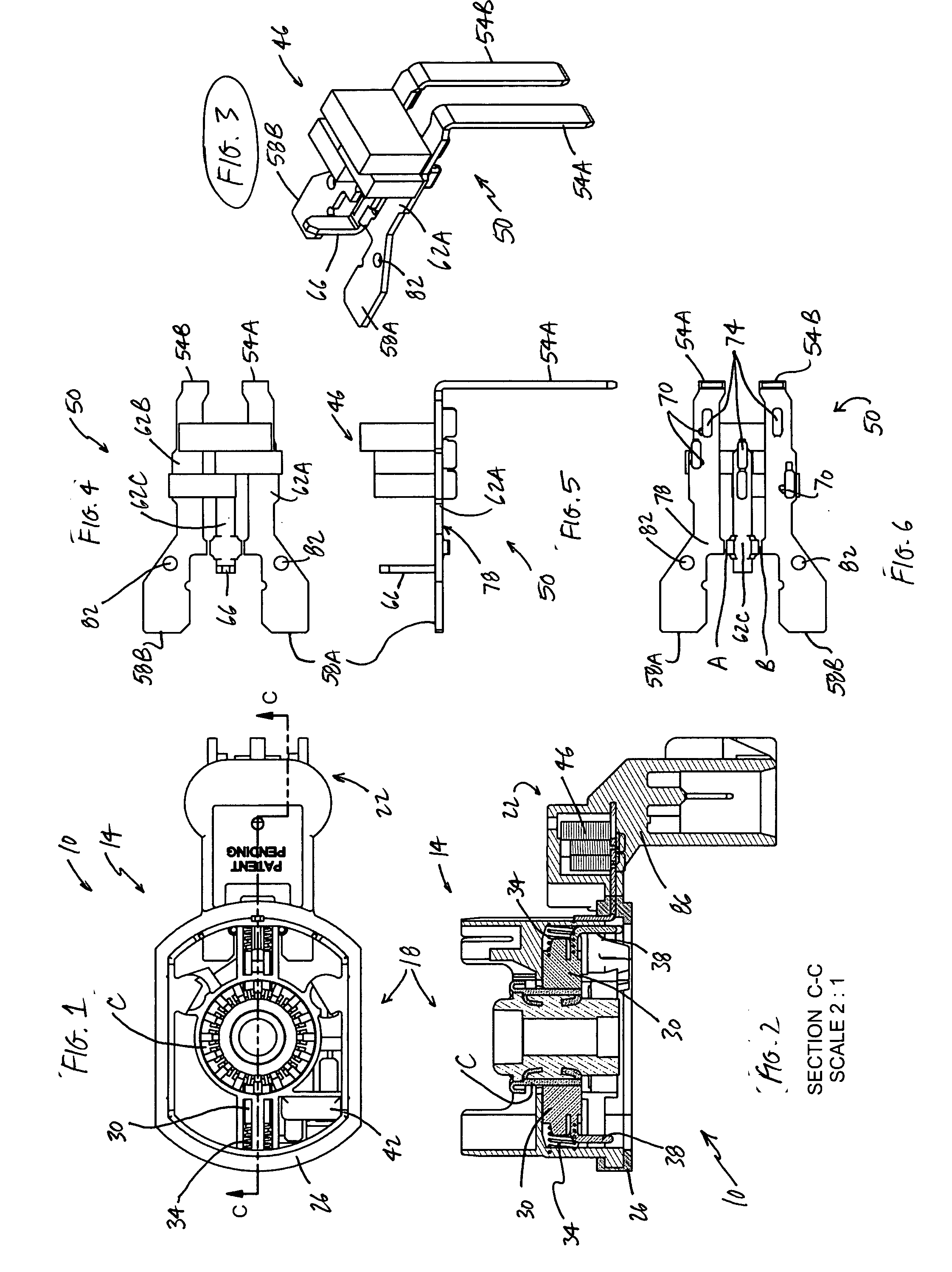
[0007] Presently preferred manufacturing techniques associated with the invention permit pre-assembly of the lead frame. As a result, multiple leaded electrical components may be securely connected to the lead frame prior to its incorporation into the brush card assembly. Thereafter, the pre-assembled lead frame may have a housing molded around it or be placed into a cavity of a pre-molded brush card housing and a cover molded over the lead frame. Brushes, springs, and other ancillary equipment then may be added within the housing and all electrical connections welded or soldered together. Because the electrical components of the lead frame need be stabilized only during the overmolding process, tooling associated with the molding (rather than retainer guides) may effect any needed stabilization of the components.

Problems solved by technology

These mountings may be difficult to effect, however, given the geometries and space limitations of the housings involved.
Mounting the components in this manner likewise may be more expensive than optimal.
Existing space limitations mandate that the electrical components be surface-mount, rather than leaded, devices, however.
These limitations result in inadequate performance of the RFI suppression components in certain conditions.
Although preferable in some respects to other approaches, this approach—with retainer guides and only two-conductor lead frames—is not optimal for at least some brush assemblies.

Method used


Image

  • Brush assemblies
  • Brush assemblies

Examples


Embodiment Construction

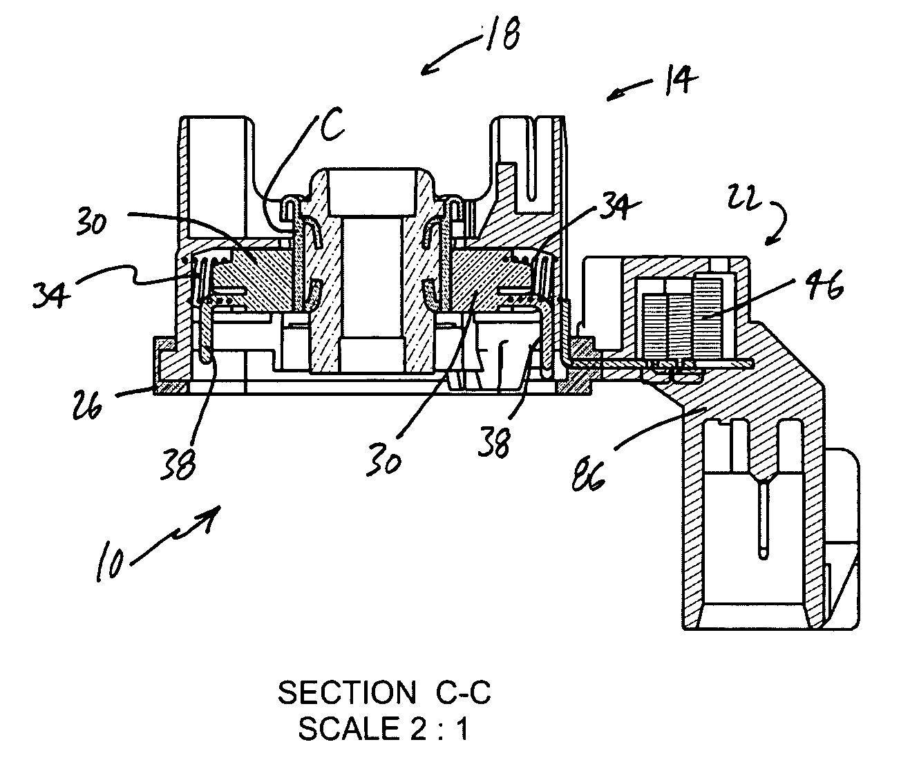
[0022] Shown in FIGS. 1-2 is an exemplary brush card assembly 10 of the present invention together with commutator C of an electric motor. Assembly 10 includes housing 14, which may comprise brush card housing 18 and lead frame housing 22. Housing 14 preferably is formed of molded plastic or other thermoplastic material that is electrically insulating, although other materials may be utilized instead if appropriate or desired. Additionally, brush card housing 18 and lead frame housing 22 preferably are integrally formed, although they need not necessarily be so created.

[0023] Also depicted in FIGS. 1-2 is seal material 26. Frequently made of Santoprene, seal material 26 is friction fitted or otherwise attached to housing 14. When assembly 10 is positioned within a device for use as part of an electric motor, material 26 may effectively seal against a surface of the device and thereby inhibit debris from entering housing 14. Those skilled in the relevant art will recognize that seal...


PUM


Abstract

Detailed are brush assemblies for electric motors. The assemblies may include lead frames to which leaded electrical components are mounted directly. The lead frames additionally may include two or more conductors and be positioned remote from the brushes of the assemblies.

Description

FIELD OF THE INVENTION [0001] This invention relates to brush assemblies for electric motors and more particularly, although not necessarily exclusively, to such assemblies in which leaded electrical components are mounted directly to lead frames. BACKGROUND OF THE INVENTION [0002] Brush assemblies for use as parts of electric motors are disclosed in numerous patents. Two of many examples of such patents are U.S. Pat. No. 6,664,701 to Ortt, et al. and U.S. Pat. No. 5,990,594 to Hyatt, Jr., et al., the contents of which are incorporated herein in their entireties by this reference. Considered generally, such assemblies house brushes which, in operation, contact a commutator to complete an electrical circuit between the commutator and a power source and cause the commutator to rotate. [0003] Some existing brush assemblies include brush card housings in which electrical components are mounted, typically for radio-frequency interference (RFI) suppression. Examples of such components inc...

Claims


Application Information

Patent Timeline
IPC IPC(8): H02K5/14H02K5/22H02K11/00H02K11/02
CPCH02K5/148H02K11/026H02K5/225
Inventor HOCKADAY, SHEPARD LYNNCORN, GEORGE DAVID JR.SUMMERS, DAVIDVONKCHALEE, PIMOL BALLARD
Owner ENERGY CONVERSION SYST HLDG
Learn More