

Electrostatic capacity type liquid state detecting sensor
a technology of electrostatic capacity and liquid state detection, which is applied in the direction of liquid/fluent solid measurement, level indicators by physical variable measurement, instruments, etc., can solve the problems of lowering the detection accuracy of the sensor, unable to achieve suitable electrostatic capacity measurement and therefore suitable detection of the liquid state, etc., to achieve the effect of accurately detecting the liquid sta
Inactive Publication Date: 2005-12-29
NGK SPARK PLUG CO LTD
View PDF5 Cites 17 Cited by
- Summary
- Abstract
- Description
- Claims
- Application Information
AI Technical Summary
Benefits of technology
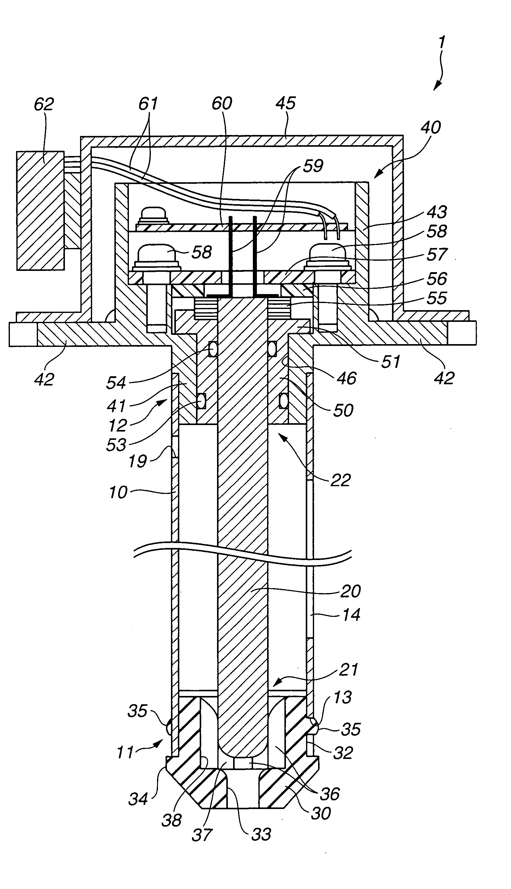
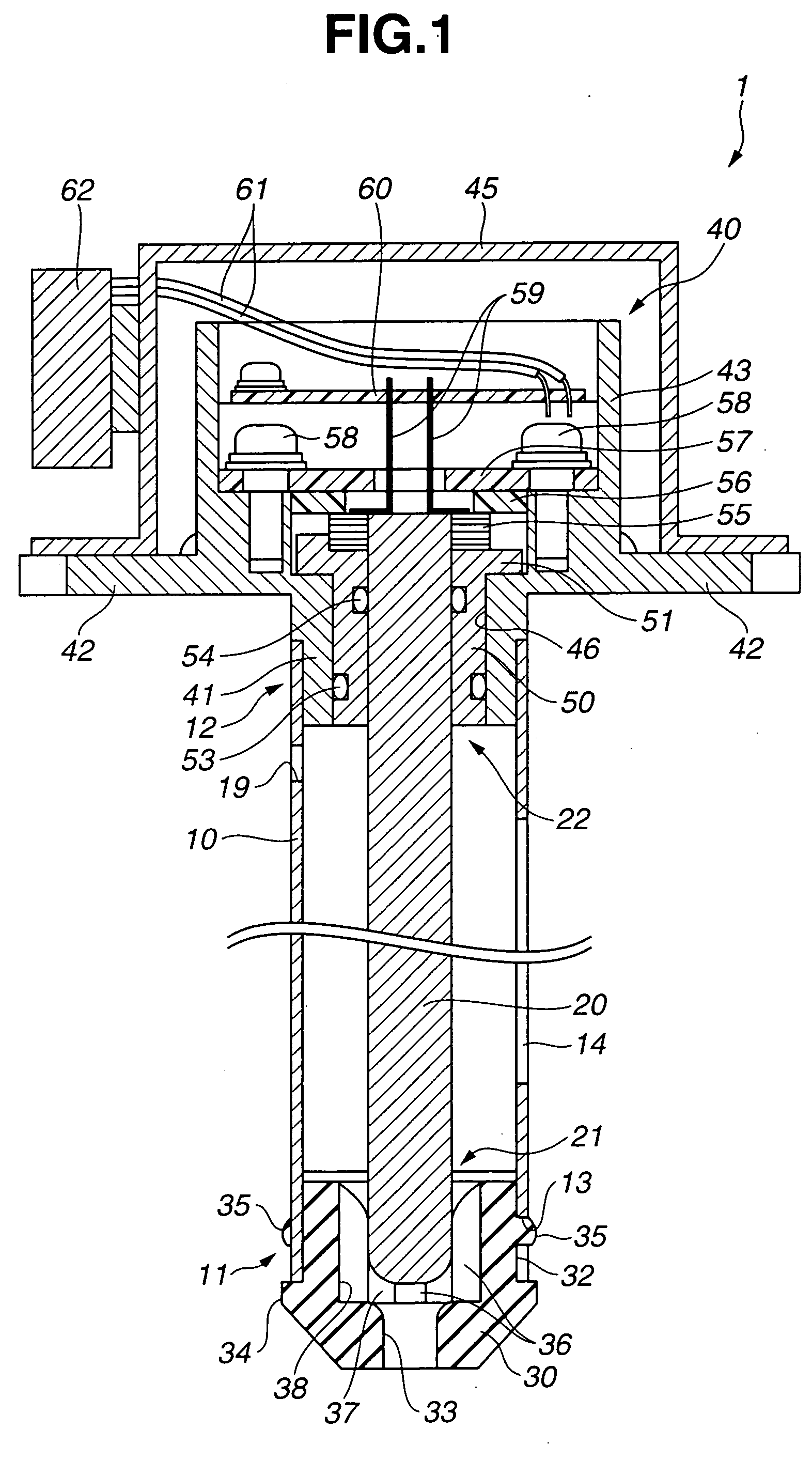
[0020] In the electrostatic capacity type liquid state detecting sensor, the sealing member is disposed as described above for preventing the liquid from flowing out from the rear end side through an opening between the outer surface of the inner electrode and the inner surface of the insulation support member. However, in case the liquid is electrically conductive as urea water, forming the insulation layer only on an outer surface portion of the inner electrode that protrudes from a front end of the insulation support member causes a possibility that the sensor becomes unable to detect the liquid state correctly due to a short between the outer electrode and the inner electrode when the container is filled with electrically conductive liquid so as to allow the liquid to
Problems solved by technology
In case the range of detectable electrostatic capacity is narrower, it is inevitable to utilize electronic parts having a high accuracy in order to improve the detection accuracy of the sensor, thus causing a problem that the sensor unit including a detection circuit becomes expensive.
Further, the rate of the floating capacity caused by the circuit structure such as a wiring pattern of the sensor to the detectable electrostatic capacity becomes larger, so that the floating cap
Method used
View moreImage
Smart ImageViewing Examples

Examples
 PUM
 Abstract
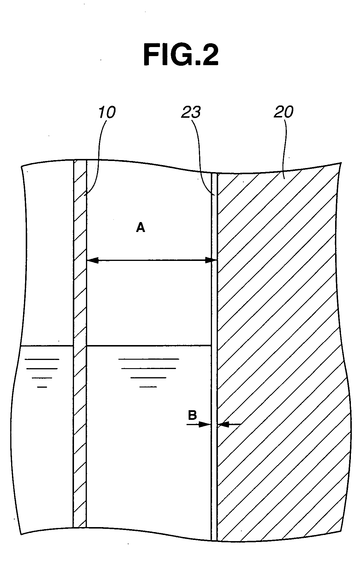
An electrostatic capacity type liquid state detecting sensor includes an outer tubular electrode, and an inner electrode disposed within the outer tubular electrode and having an insulation layer at an outer surface portion to be brought into contact with liquid contained in a container for detection of a state of the liquid, wherein the thickness of the insulation layer is less than 500 μm and not less than 100 μm.
Description
BACKGROUND OF THE INVENTION [0001] The present invention relates to an electrostatic capacity type liquid state detecting sensor for detecting a state of liquid contained in a container. [0002] The exhaust gases emitted from a diesel vehicle contain nitride oxides (NOx) other than carbon monoxide (CO) and hydrocarbon (HC). In recent years, it has been practiced to reduce the harmful nitride oxides into non-harmful gas. For example, it has been proposed to dispose at the exhaust muffler of the diesel vehicle an NOx selective reduction (SCR) catalyst, while keeping urea water that serves as reduction agent in a container separately installed on the vehicle, and inject the urea water into the catalyst to thereby reduce NOx into a non-harmful gas such as N2. With this system, if the urea water is used up, it becomes impossible to urge NOx to be reduced so that a large amount of NOx is emitted from the vehicle. To solve this problem, there have been proposed various steps such as a step ...
Claims
Login to View More Application Information
Patent Timeline
 IPC IPC(8): G01F23/26G01N27/22G01N33/28G01R27/26
CPCG01F23/268G01N27/226
InventorSATO, YOSHIKUNIYAMAMOTO, TAKASHISASANUMA, TAKEO
OwnerNGK SPARK PLUG CO LTD