WDM signal light monitoring apparatus, WDM system and WDM signal light monitoring method

a signal light and monitoring apparatus technology, applied in the field of wdm signal light monitoring apparatus, wdm system and a, can solve the problems of accumulating noise from amplifiers (spontaneous emission), difficult to accurately detect the presence or absence of signal light of each channel, and difficult to detect the presence or absence of signal light using phase modulation schemes

Inactive Publication Date: 2012-01-05
NEC CORP
View PDF3 Cites 8 Cited by
  • Summary
  • Abstract
  • Description
  • Claims
  • Application Information

AI Technical Summary

Benefits of technology

[0011]An object of the present invention is to provide a WDM signal light monitoring apparatus, a WDM system and a WDM signal light monitoring method which solve the above problem, that is, the problem that accuracy of detecting the presence or absence of a signal light of each of the channels is reduced due to the effect of ASE noise, as the symbol rate increases in the WDM system.
[0020]With the above configurations, the present invention can detect the presence or absence of the signal light of each of the channels with high accuracy in the WDM system.

Problems solved by technology

Moreover, ASE (Amplified Spontaneous Emission) noise is accumulated by passing through optical amplifiers at many stages in the transmission path.
Thus, it is difficult to detect the presence or absence of the signal light using the phase modulation scheme.
Thus, it is difficult to accurately detect the presence or absence of the signal light of each of the channels, due to an effect of the ASE noise.

Method used


Image

  • WDM signal light monitoring apparatus, WDM system and WDM signal light monitoring method
  • WDM signal light monitoring apparatus, WDM system and WDM signal light monitoring method
  • WDM signal light monitoring apparatus, WDM system and WDM signal light monitoring method

Examples


first exemplary embodiment

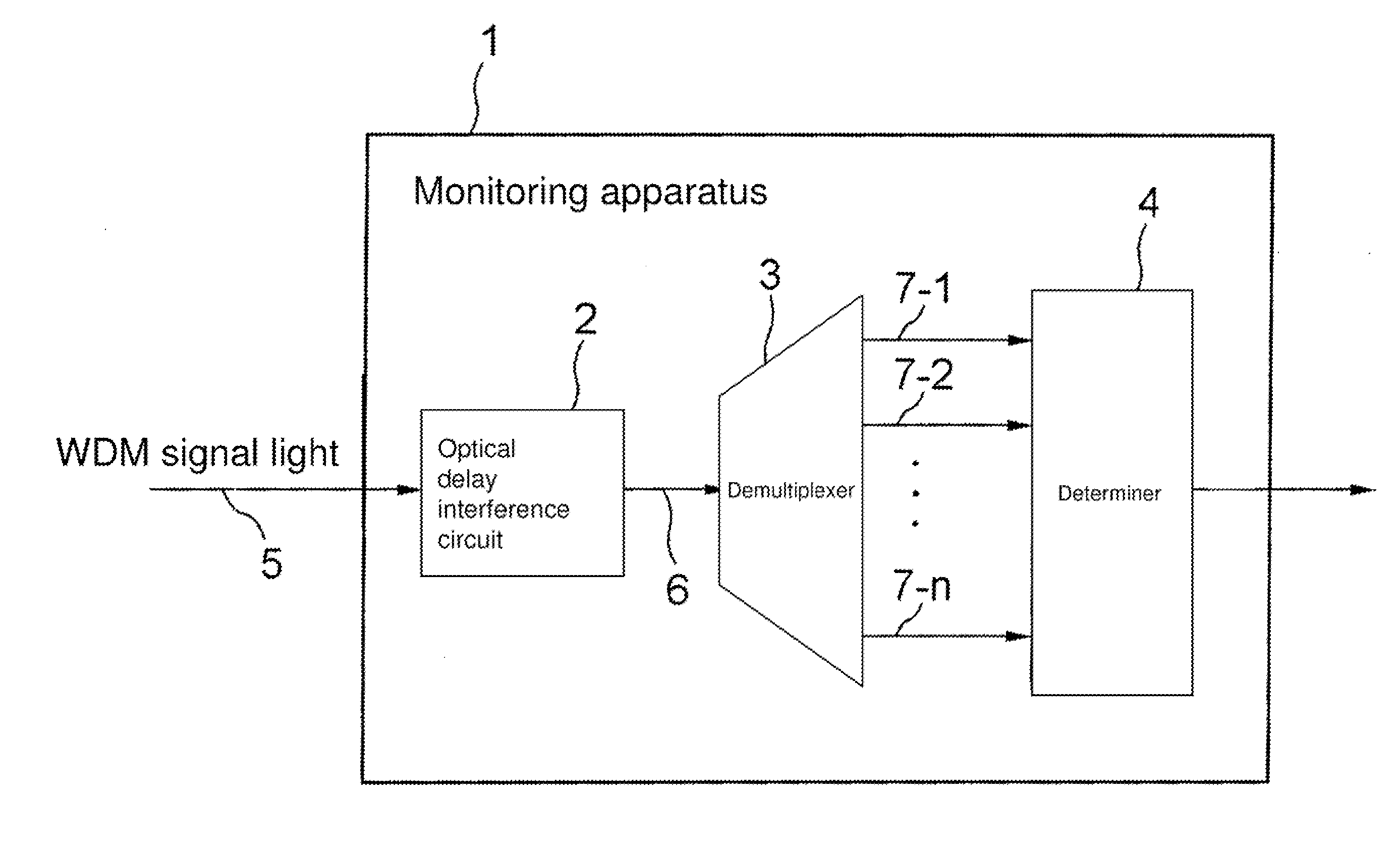
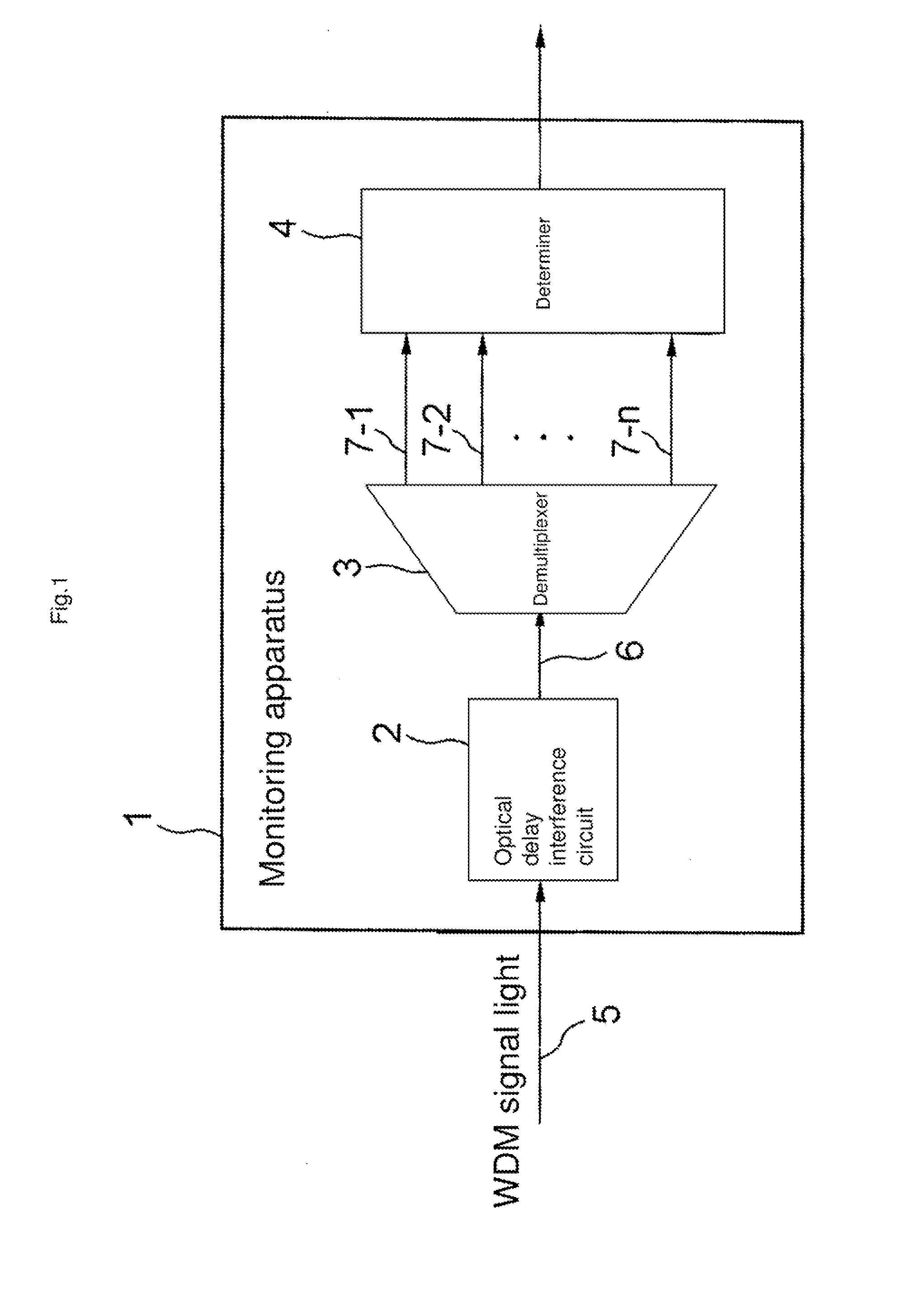
[0033]With reference to FIG. 1, WDM signal light monitoring apparatus 1 according to a first exemplary embodiment includes optical delay interference circuit 2, demultiplexer 3 and determiner 4.

[0034]Optical delay interference circuit 2 inputs phase-modulated WDM signal light 5, and outputs intensity-modulated WDM signal light 6. Specifically, optical delay interference circuit 2 first demultiplexes WDM signal light 5 into a first WDM signal light and a second WDM signal light at approximately the same level. Next, optical delay interference circuit 2 gives a predetermined delay difference between the first WDM signal light and the second WDM signal light. For example, if a modulation scheme of WDM signal light 5 is Differential Phase Shift Keying (DPSK), one signal light from among the first WDM signal light and the second WDM signal light is delayed by a time of one symbol relative to the time of one symbol of the other WDM signal light. Next, optical delay interference circuit 2 ...

second exemplary embodiment

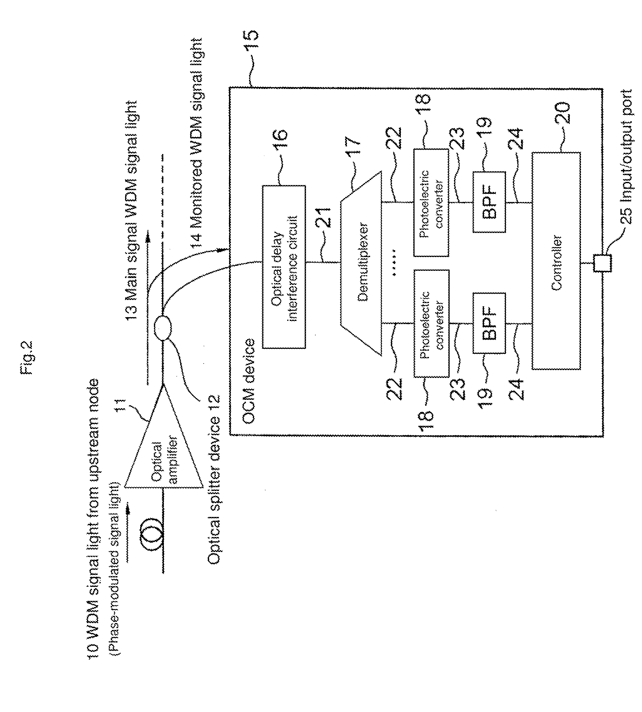
[0040]With reference to FIG. 2, the wavelength division multiplexing system as a second exemplary embodiment is shown. In FIG. 2, WDM signal light 10 transmitted from an upstream node is a signal light in which the number of channels is n (≧1), the wavelength of each channel is λ1 to λn, and the modulation scheme is phase modulation.

[0041]WDM signal light 10 goes through optical amplifier 11, and is split into main signal WDM signal light 13 and monitored WDM signal light 14 by optical splitter device 12. Main signal WDM signal light 13 is transmitted to a downstream node, and monitored WDM signal light 14 is inputted to OCM (Optical Channel Monitor) device 15 which is a monitoring apparatus.

[0042]OCM device 15 includes optical delay interference circuit 16, demultiplexer 17, photoelectric converters 18, band-pass filters (BPF) 19 which are the filtering circuits, and controller 20. Note that a determiner includes photoelectric converters 18, band-pass filters 19 and controller 20.

[...

third exemplary embodiment

[0072]With reference to FIG. 6, OCM device 15A which is the monitoring apparatus according to a third exemplary embodiment is different from OCM device 15 shown in FIG. 2 in that OCM device 15A includes low-pass filter (LPF) 19A instead of band-pass filter 19.

[0073]FIG. 7 is a diagram showing an example of a relationship among the frequency characteristics of the signal light and the ASE signal which enter photoelectric converter 18 shown in FIG. 6, the frequency band of the PD included in photoelectric converter 18, and cutoff frequency fH of low-pass filter 19A.

[0074]In the present exemplary embodiment, the signal at a frequency equal to or higher than cutoff frequency fH is removed by low-pass filter 19A. As described above, the level difference between the signal light and the ASE signal which enter photoelectric converter 18 gradually becomes smaller as the frequency becomes higher. In the frequency band in which the level difference between the signal light and the ASE signal ...


PUM


Abstract

A WDM signal light monitoring apparatus includes an optical delay interference circuit, a demultiplexer and a determiner. The optical delay interference circuit demultiplexes a phase-modulated WDM signal light, gives a delay difference to the demultiplexed WDM signal lights, then multiplexes the demultiplexed WDM signal lights, and thereby generates an intensity-modulated WDM signal light. The demultiplexer demultiplexes the intensity-modulated WDM signal light into signal lights of respective channels, and outputs the demultiplexed signal lights. The determiner determines the presence or absence of the signal light of each of the channels, based on the signal lights outputted from the demultiplexer.

Description

[0001]This application is based upon and claims the benefit of priority from Japanese patent application No. 2010-148543, filed on Jun. 30, 2010, the disclosure of which is incorporated herein in its entirety by reference.BACKGROUND OF THE INVENTION[0002]1. Field of the Invention[0003]The present invention relates to a WDM signal light monitoring apparatus, a WDM system and a WDM signal light monitoring method which detect the presence or absence of a signal light of each of the channels.[0004]2. Description of the Related Art[0005]In recent years, an optical transmission apparatus using a Wavelength Division Multiplexing (WDM) technique has been generally introduced in areas ranging from a backbone to a metropolitan area because of increased communication capacity (a bit rate of 40 to 100 Gbps). In a WDM system constructed with such an optical transmission apparatus, the presence or absence of a signal light of each of channels needs to be detected for performing transmission signa...

Claims


Application Information

Patent Timeline
Patent Type & Authority Applications(United States)
IPC IPC(8): H04B17/00H04B10/07H04B10/556H04J14/00H04J14/02
CPCH04B10/07955H04J14/0221H04J14/02
Inventor TOSAKI, AKIHIRO
Owner NEC CORP
Why Eureka
Try Eureka