Full charge control apparatus for onboard battery
a technology of full charge control and battery, which is applied in the direction of road transportation emission reduction, transportation and packaging, instruments, etc., can solve the problems of battery temperature detection with high accuracy, battery deterioration, and sulfation which will accelerate deterioration, so as to prevent deterioration of battery and improve the accuracy of battery temperature detection.
- Summary
- Abstract
- Description
- Claims
- Application Information
AI Technical Summary
Benefits of technology
Problems solved by technology
Method used
Image
Examples
first embodiment
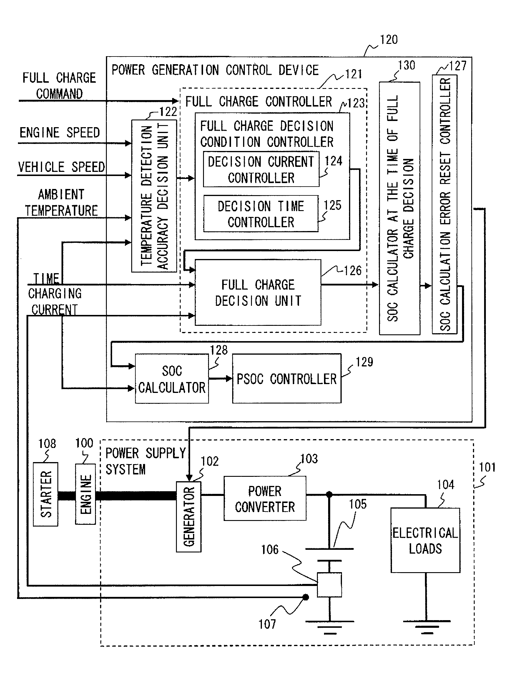
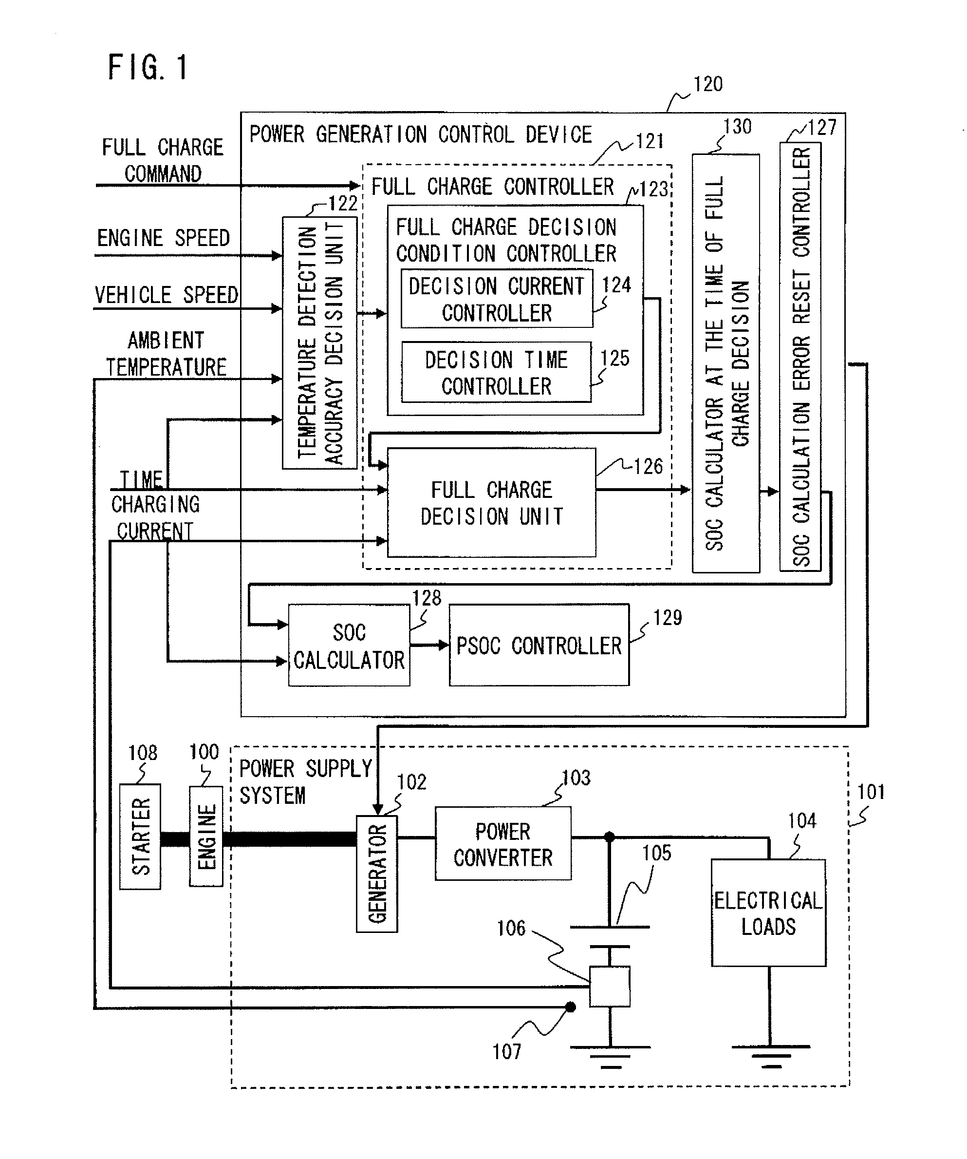
[0019]FIG. 1 is a configuration diagram of a full charge control apparatus for an onboard battery according to a first embodiment of the present invention, in which hardware sections illustrated are elements extracted as being particularly related to the working of the full charge control apparatus described hereinbelow.
[0020]An engine 100 mounted on a vehicle is started by a starter 108 and outputs a torque used for turning a generator 102 which constitutes part of a power supply system 101. It is to be noted that FIG. 1 does not illustrate a driving force output system of the engine 100 that is used for producing a driving force for the vehicle.
[0021]A power converter 103 converts AC power supplied from the generator 102 into DC power by full-wave rectification of the AC power and supplies the DC power thus obtained to electrical loads 104, such as headlights, an interior lamp and the battery 105. A current sensor 106 detects charging and discharging currents of the battery 105 wh...
second embodiment
[0049]Now, the full charge control operation performed when the full charge controller 121 illustrated in FIG. 1 receives the full charge command in a case where the full charge decision condition controller 123 includes the decision time controller 125 is described with reference to the timing chart of FIG. 5. The following discussion deals with a case where the power generation control device 120 executes processing step 306 when the judgment result in step 304 is in the negative (No in step 304) in the flowchart of FIG. 3.
[0050]Referring to FIG. 5, waveform 501 represents an IG flag, which indicates ON / OFF states of the ignition switch. The IG flag 501 becomes ON at engine start and becomes OFF at engine stop. Waveform 502 represents ON / OFF states of a full charge command flag which becomes ON during execution of the full charge operation and becomes OFF during other than the full charge operation. Waveform 503 represents the generation voltage of the generator 102, waveform 504 ...
PUM
 Abstract
Description
Claims
Application Information
 - R&D
- Intellectual Property
- Life Sciences
- Materials
- Tech Scout
- Unparalleled Data Quality
- Higher Quality Content
- 60% Fewer Hallucinations
Browse by: Latest US Patents, China's latest patents, Technical Efficacy Thesaurus, Application Domain, Technology Topic, Popular Technical Reports.
© 2025 PatSnap. All rights reserved.Legal|Privacy policy|Modern Slavery Act Transparency Statement|Sitemap|About US| Contact US: help@patsnap.com


