Amplifying circuit with variable supply voltage

Active Publication Date: 2005-12-29
REALTEK SEMICON CORP
View PDF3 Cites 72 Cited by
  • Summary
  • Abstract
  • Description
  • Claims
  • Application Information

AI Technical Summary

Benefits of technology

[0008] According to another embodiment of the present invention, the method for adjusting the supply voltage includes: generating a control

Problems solved by technology

However, most amplifiers do not utilize pow

Method used


Image

  • Amplifying circuit with variable supply voltage
  • Amplifying circuit with variable supply voltage
  • Amplifying circuit with variable supply voltage

Examples


Embodiment Construction

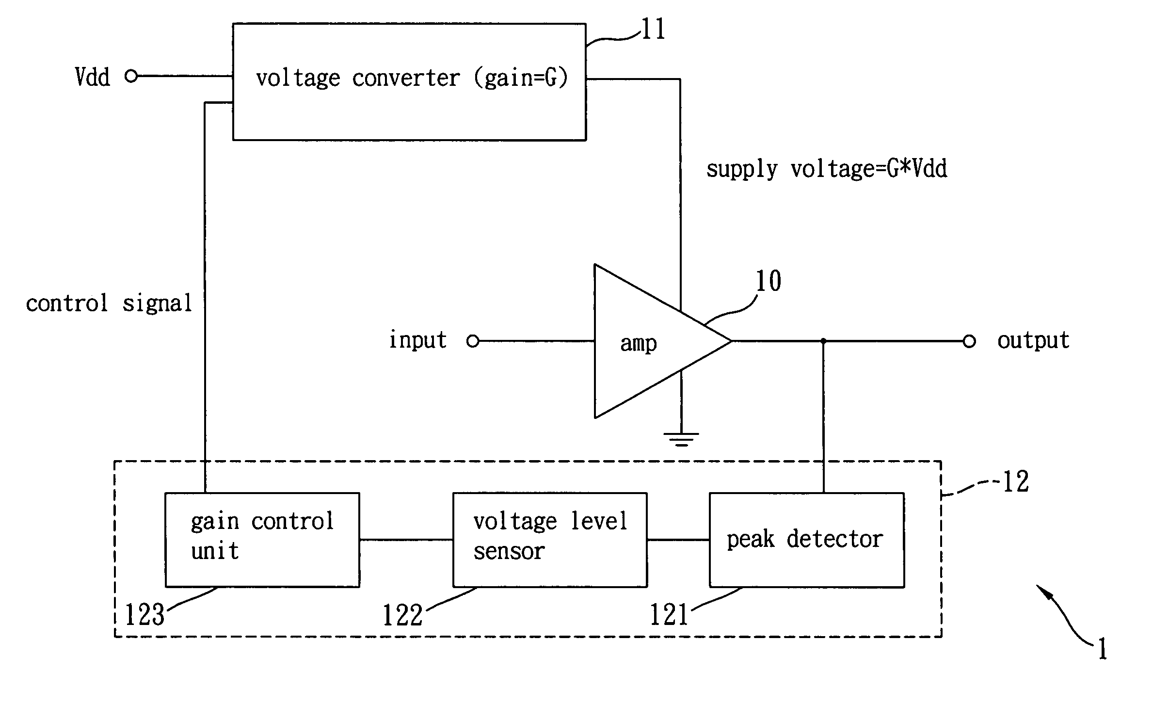
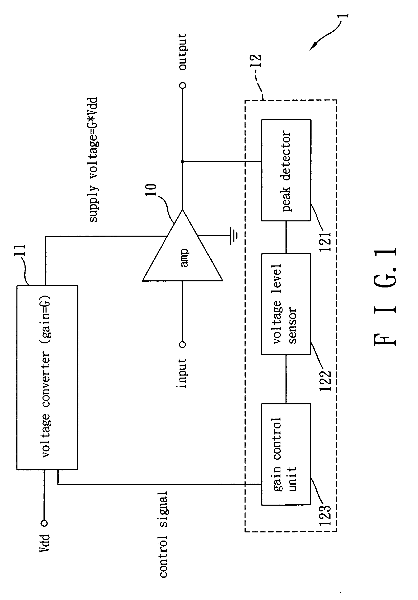
[0013]FIG. 1 is a block diagram of a preferred embodiment of the amplifying circuit according to the present invention. As shown in FIG. 1, the amplifying circuit 1 includes an amplifier 10, a voltage converter 11, and a control device 12. The voltage converter 11 coupled to the amplifier 10 can transfer a received source voltage Vdd into a supply voltage, and provide the supply voltage to the amplifier 10. If the gain of the voltage converter 11 is G, the supply voltage should be G*Vdd. The voltage converter 11 can further dynamically adjust the gain G according to a control signal outputted by the control device 12 as described in the following.

[0014] The control device 12 can generate the control signal according to an output signal of the amplifier 10. In this embodiment, the control device 12 includes a peak detector 121, a voltage level sensor 122 and a gain control unit 123. The peak detector 121 coupled to an output of the amplifier 10 is for detecting a voltage peak of the...


PUM


Abstract

An amplifying circuit with a variable supply voltage and a method thereof are disclosed. The amplifying circuit employs a voltage converter to adjust the supply voltage, thereby upgrading the energy efficiency of the circuit. The circuit also includes a control device, which can generate a control signal for controlling the voltage converter according to an output signal or input signal of the circuit.

Description

BACKGROUND OF THE INVENTION [0001] (a). Field of the Invention [0002] The present invention relates in general to electronic circuits, and more particularly to amplifying circuits with a variable supply voltage. [0003] (b). Description of the Prior Arts [0004] Amplifiers are very common circuit components. However, most amplifiers do not utilize power efficiently. In general, only a part of the energy provided to an amplifier will be used to drive the amplifier outputting an output signal according to an input signal. Most of the energy is wasted. SUMMARY OF THE INVENTION [0005] It is therefore an object of the present invention to provide an amplifying circuit with a variable supply voltage for solving the above-mentioned problems. [0006] Another object of the present invention is to provide a method for adjusting a supply voltage provided to an amplifier that generates an output signal according to an input signal, thereby solving the above-mentioned problems. [0007] According to ...

Claims


Application Information

Patent Timeline
IPC IPC(8): H02M3/07H03F1/02H03F3/04H03G1/00H03G3/00H03G3/30
CPCH02M3/07H03F1/0238H03G3/3042H03G1/0088H03G3/004H03F2200/435
Inventor LEE, CHAO-CHENGCHEN, TZUNG-MINGFENG, CHIEH-MIN
Owner REALTEK SEMICON CORP
Why Eureka
Try Eureka