Tube pump and liquid ejection apparatus

Inactive Publication Date: 2005-12-29
SEIKO EPSON CORP
View PDF10 Cites 13 Cited by
  • Summary
  • Abstract
  • Description
  • Claims
  • Application Information

AI Technical Summary

Benefits of technology

[0010] Accordingly, it is an objective of the present invention to provide an impr

Problems solved by technology

At this stage, since the two portions have greatly different surface conditions, a noise may be caused due to an impact between the roller 3 and the tube 1.
Further, when the roller 3 proceeds from the downstre

Method used


Image

  • Tube pump and liquid ejection apparatus
  • Tube pump and liquid ejection apparatus
  • Tube pump and liquid ejection apparatus

Examples


third embodiment

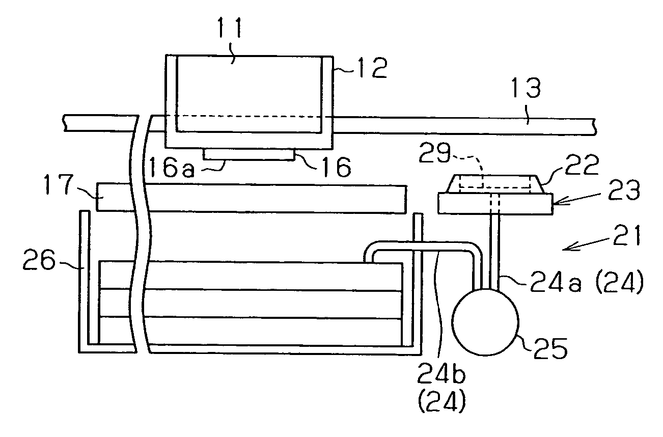
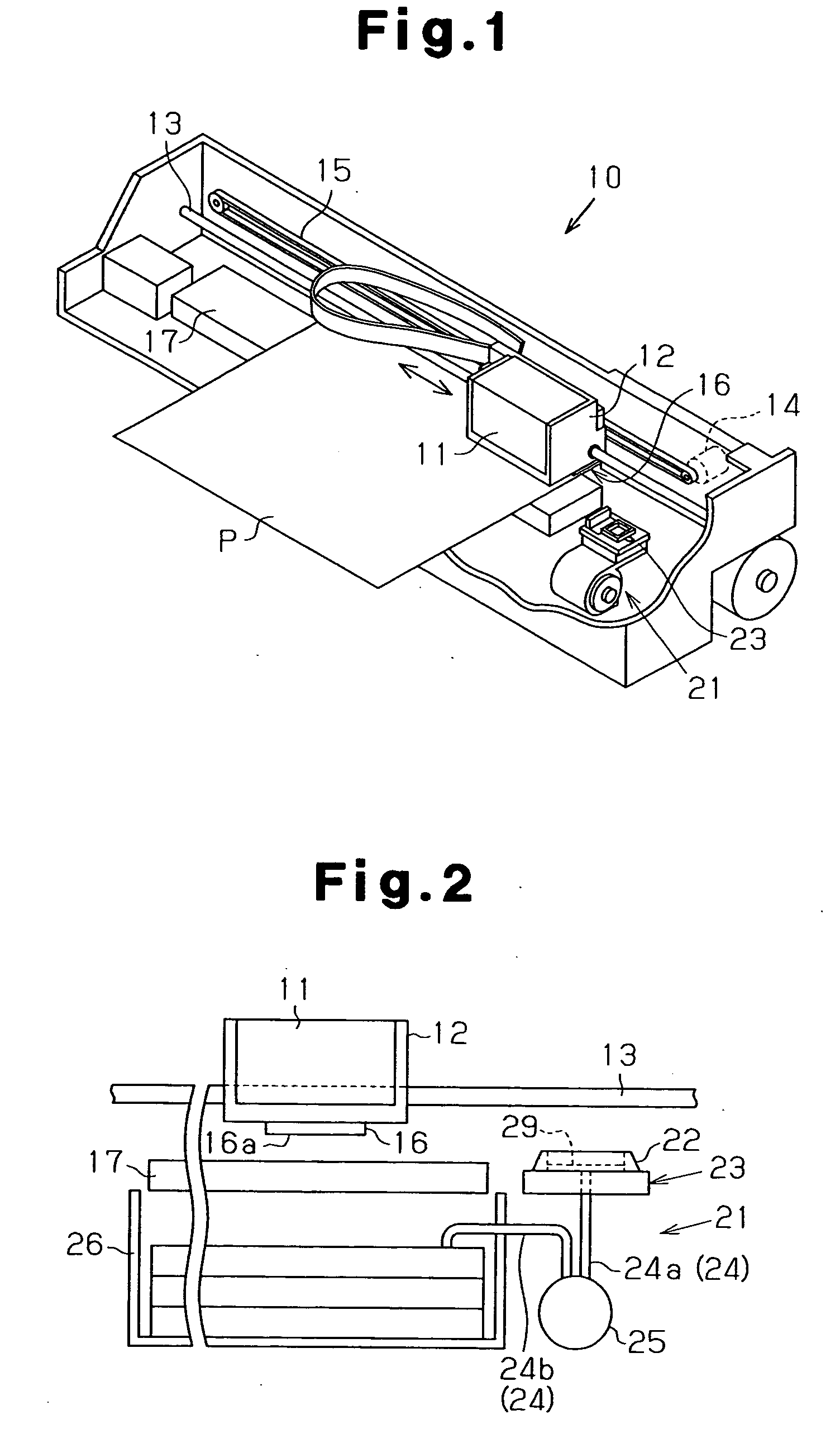
[0105]FIGS. 17 and 18 show an example of an inkjet recording apparatus, a liquid ejection apparatus including a tube pump according to the present invention.

[0106] As shown in FIG. 17, the accommodating case 31, which is a constituent of the tube pump 25 of the head cleaning device 21 of the inkjet recording apparatus 10, includes an assistant member 121, in place of the assistant member 111 of the second embodiment.

[0107] Like the assistant member 111, the assistant member 121 is shaped as a substantially triangular pole with the axial dimension equal to that of the inner wall 31a of the case 31. The assistant member 121 is formed from an elastic material with hardness sufficient for suppressing major elastic deformation.

[0108] In the substantially same manner as the assistant member 111 of the second embodiment, the assistant member 121 includes a triangular shape that extends along the inward portions of the outer circumferential surface of the tube 24 passing through the openi...

fourth embodiment

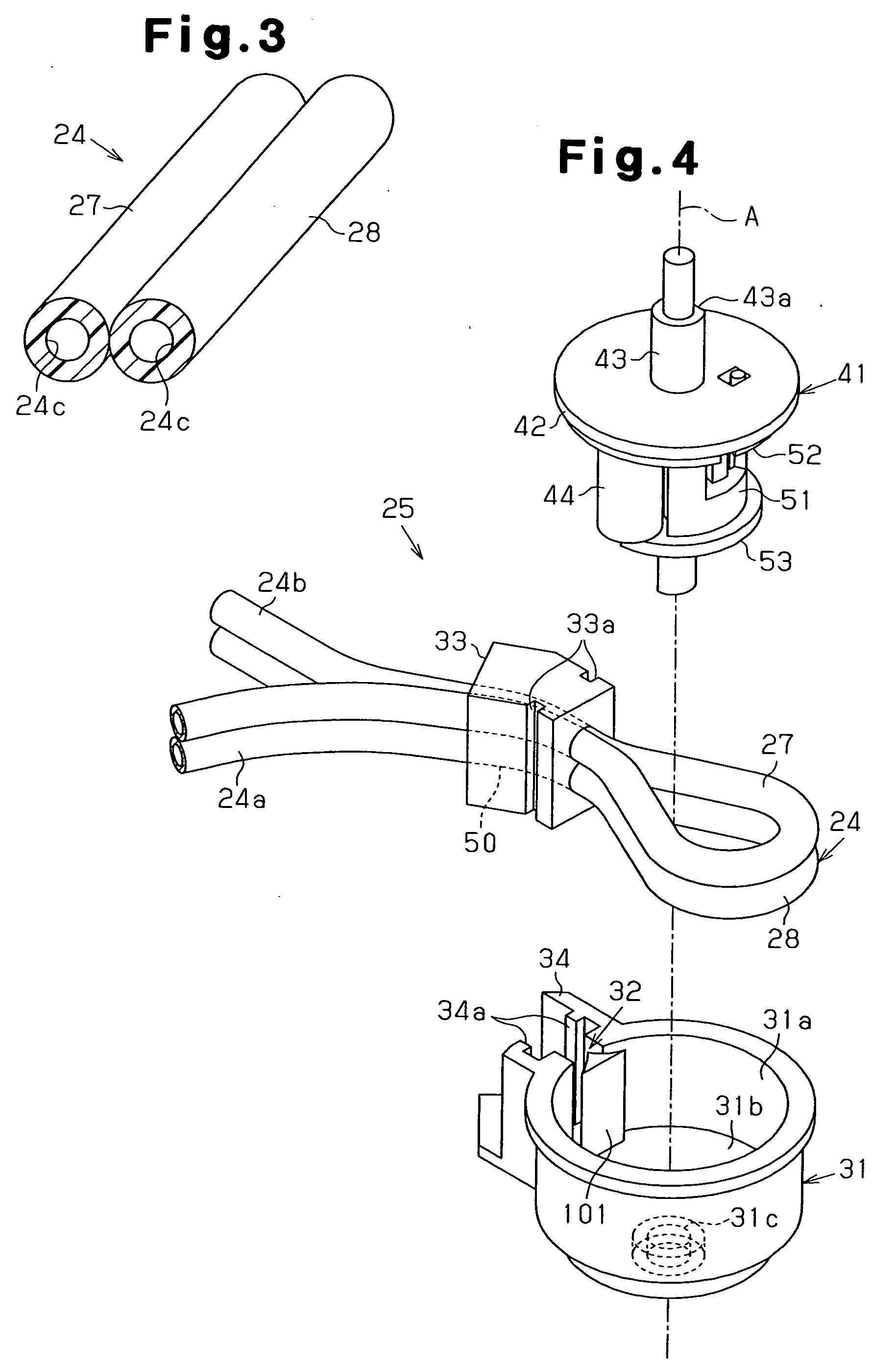
[0118] FIGS. 19 to 24 show an example of an inkjet recording apparatus according to the present invention, a liquid ejection apparatus including a tube pump. As shown in FIG. 19, a flexible tube 24 includes two tube members 27, 28 formed of flexible material such as silicone rubber. The tube members 27, 28 are connected together at a connecting portion 227.

[0119] With reference to FIG. 20, a tube pump 25 includes an accommodating case 31, a fixing block 33 functioning as a fastening portion, and a pressing device 41. An opening 32, or a cutaway portion, is defined in an inner wall 31a, or the inner circumferential surface of the accommodating case 31. The opening 32 is defined by removing a section of the inner wall 31a from an upper position to a lower position in the vicinity of a bottom 31b.

[0120] As illustrated in FIG. 20, the fixing block 33 is received by an attaching portion 34 for defining an outlet portion. Referring to FIG. 21, the fixing block 33 includes an insertion bo...

fifth embodiment

[0144] The fifth embodiment has the following advantages.

[0145] (1) In the fifth embodiment, the damper portion 260, which is formed of elastic material, has a plate-like shape that is substantially identical to that of the clamped portion 249. The damper portion 260 extends in a radial inward direction of the accommodating case 31. When moving from the downstream portion 24b to the upstream portion 24a, the roller 44 squeezes the bent tube portion 245 through the damper portion 260. The roller 44 is thus prevented from hitting the bent tube portion 245, such that the roller 44 is passed smoothly from the downstream portion 24b to the upstream portion 24a. Further, since the roller 44 squeezes the bent tube portion 245 through the damper portion 260 when moving from the downstream portion 24b to the upstream portion 24a, intermittent ink drawing or discharging is avoided by the tube pump 25. Also, since the damper portion 260 and the clamped portion 249 have the substantially identi...


PUM


Abstract

A flexible tube has a first portion and a second portion located close to each other in the vicinity of an opening of an accommodating case. A pressing member moves from the first portion to the second portion along the tube while pressing a portion of the tube. An assistant member is provided in the vicinity of the opening of the case. The assistant member has an assistant surface. When the pressing member passes the vicinity of the opening of the case, the assistant member transfers the pressing member from the second portion to the first portion via the assistant surface. This structure ensures a silent operation of the tube pump.

Description

CROSS-REFERENCE TO RELATED APPLICATIONS [0001] This application is a continuation-in-part application of the pending U.S. patent application Ser. No. 10 / 817,429, filed on Apr. 5, 2004, entitled “TUBE PUMP AND LIQUID INJECTION APPARATUS”BACKGROUND OF THE INVENTION [0002] The present invention relates to tube pumps and liquid ejection apparatuses, and, more particularly, to tube pumps and liquid ejection apparatuses that operate silently. [0003] Conventionally, a tube pump drawing fluid from one end and discharging it from another by generating negative pressure is known. Since this type of pump is configured simple and compact, the pump is used in different types of apparatuses that involve the use of fluid. [0004] For example, the tube pump is used in an inkjet recording apparatus (a liquid ejection apparatus), which discharges (ejects) ink (liquefied fluid) to a recording sheet through a nozzle of a recording head, forming an image on the sheet. The tube pump draws ink from the noz...

Claims


Application Information

Patent Timeline
IPC IPC(8): B41J2/165B41J2/175
CPCB41J2/17596
Inventor HARADA, SHUHEIKUWADA, SHOZO
Owner SEIKO EPSON CORP
Why Eureka
Try Eureka