Droplet ejecting head

Active Publication Date: 2005-12-29
BROTHER KOGYO KK
View PDF4 Cites 11 Cited by
  • Summary
  • Abstract
  • Description
  • Claims
  • Application Information

AI Technical Summary

Benefits of technology

[0012] The prevent invention has been developed in view of the above-described situations, and it is th

Problems solved by technology

Therefore, the shape of the nozzle holes considerably affects the ink ejection performance.
Even when the diameters at the opposite open ends and the tapering shape of the nozzle hole are appropriately specified, however, it is difficult to obtain the nozzle holes of the shape precisely as designed.
This is because of that in actual laser beam machining the laser beam can not be accurately focused at a point, and results in a rounded interse

Method used


Image

  • Droplet ejecting head
  • Droplet ejecting head
  • Droplet ejecting head

Examples


Embodiment Construction

[0028] Hereinafter, there will be described one embodiment of the invention by referring to the accompanying drawings.

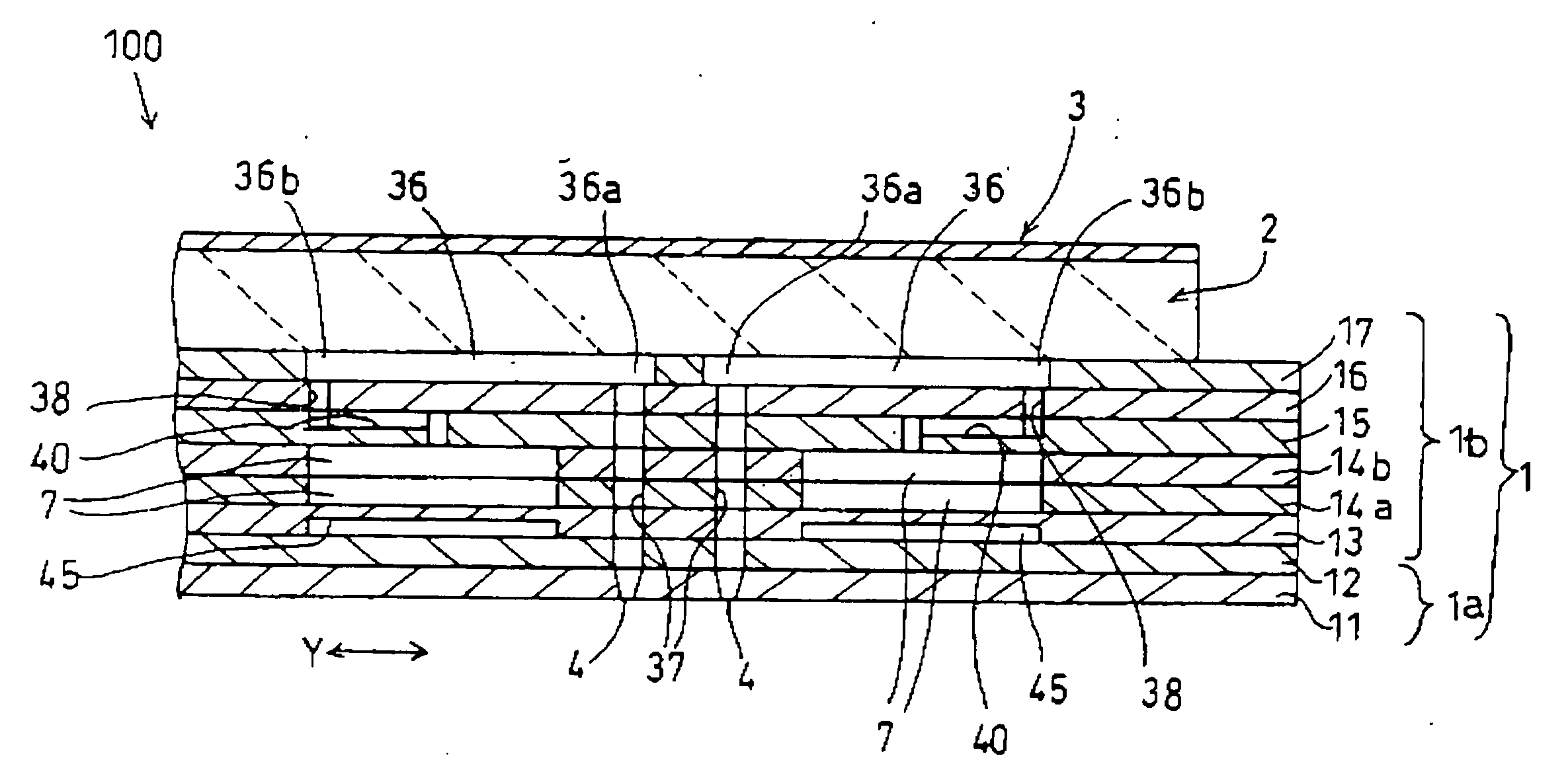
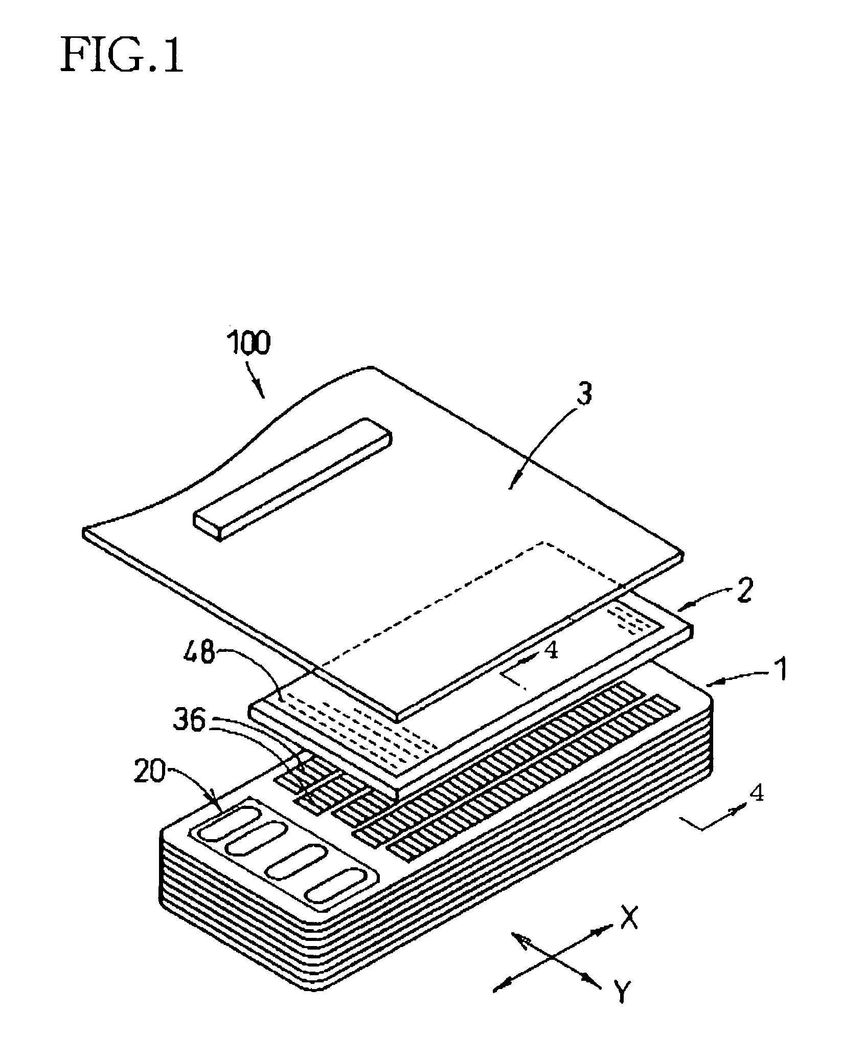
[0029] In FIG. 1, reference numeral 100 denotes a piezoelectric inkjet printhead 100 according to the embodiment of the invention. The printhead 100 includes a cavity unit 1 formed of a laminate of a plurality of metallic plates, and a planar piezoelectric actuator 2 attached to the cavity unit 1. A flexible flat cable 3 is superposed on and attached to an upper surface of the planar piezoelectric actuator 2, for connection with an external device. The lowermost one of the metallic plates of the cavity unit 1 is a nozzle plate 11 through which are formed a plurality of nozzle holes 4 to be open in an undersurface of the cavity unit 1. An ink droplet is ejected downward through each nozzle hole 4.

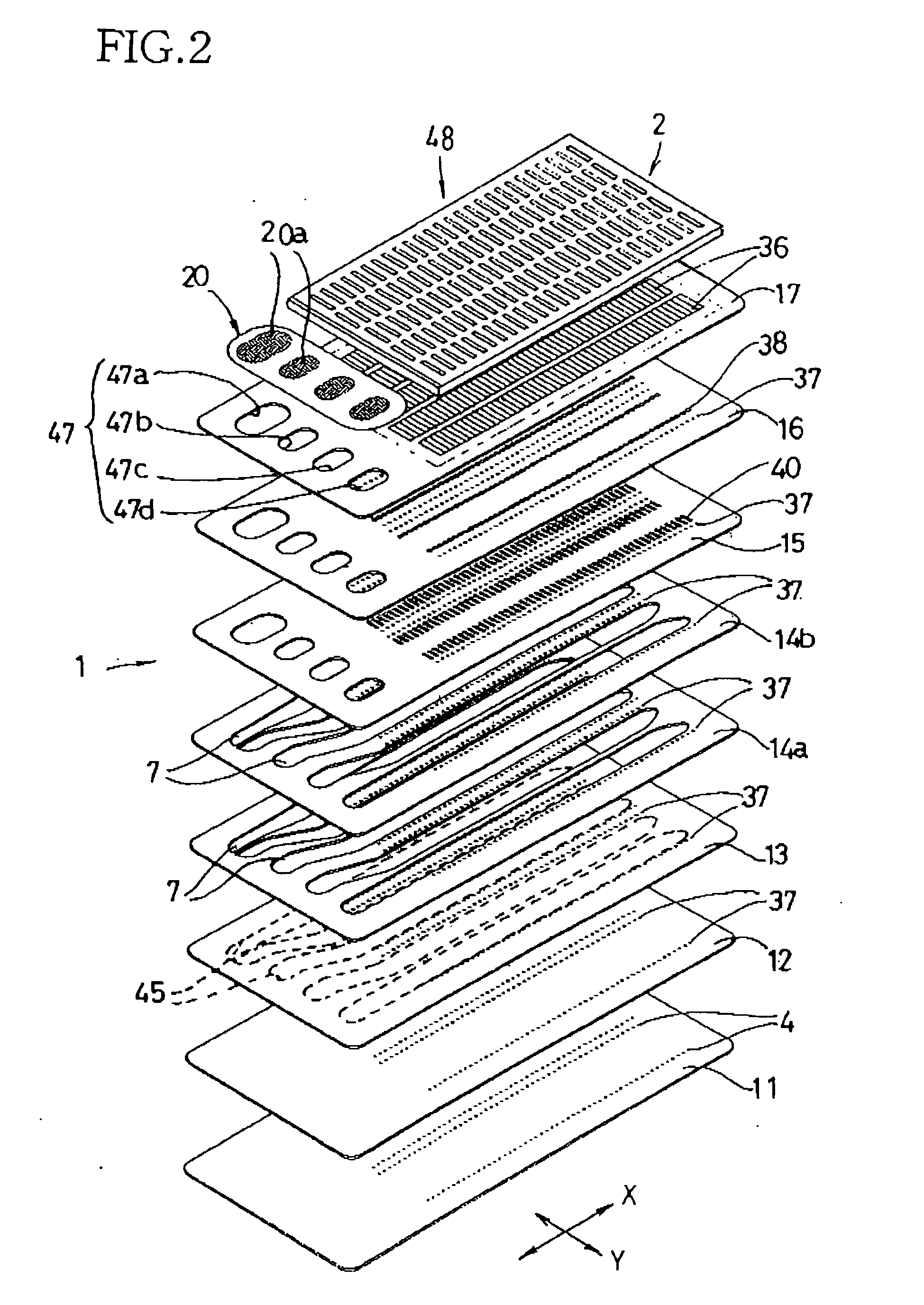
[0030] As shown in FIG. 2, in addition to the nozzle plate 11 the cavity unit 1 further comprises a spacer plate 12, a damper plate 13, two manifold plates 14a, 14b, a supp...


PUM


Abstract

A droplet ejecting head including a nozzle plate having nozzle holes each ejecting a droplet and comprising: a jetting end open at a first surface of the plate; an inflow end open at a second surface of the plate; a taper portion between the jetting end and a vicinity of the inflow end, where a diameter of the nozzle hole linearly increases from the jetting end to the vicinity so as to have a taper angle; a connecting portion comprising a surface connecting the taper portion and the inflow end, at the connecting portion the diameter increasing more greatly than at the taper angle; and where D1 and D2 respectively represent the diameter of the nozzle hole at the inflow end and at an imaginary inflow end obtained if the taper portion extends at the taper angle up to the second surface, D2<D1<1.2×D2.

Description

[0001] The present application is based on Japanese Patent Application No. 2004-179529, filed on Jun. 17, 2004, the content of which is incorporated herein by reference. BACKGROUND OF THE INVENTION [0002] 1. Field of the Invention [0003] The present invention relates to a droplet ejecting head having a nozzle hole for ejecting a droplet of a liquid or the like therethrough. Such a droplet ejecting head may be an inkjet printhead, but not limited thereto. For instance, there are also a head which ejects droplets of a material having an electrical conductivity onto a substrate to form wiring or a circuit on the substrate, and a head which ejects droplets of a solidifiable material to form a three-dimensional shape which is then solidified to obtain a three-dimensional body. [0004] 2. Description of the Related Art [0005] In such a kind of droplet ejecting head, the size and shape of the droplets are desired to be regulated with high accuracy and precision. This will be described more ...

Claims


Application Information

Patent Timeline
IPC IPC(8): B41J2/045B41J2/14B41J2/16
CPCB41J2/1433B41J2/162B41J2/1634B41J2002/14475B41J2002/14419B41J2002/14459B41J2002/14306
Inventor SEKIGUCHI, YASUHIRO
Owner BROTHER KOGYO KK
Why Eureka
Try Eureka