Injection mold capable of achieving cylinder core pulling ejection

An injection mold and ejector rod technology, which is applied in the field of creating mold processing and manufacturing, can solve problems such as the impact of ejection effect, poor ejection efficiency, and increase motion resistance, so as to reduce equipment loss and maintenance costs, and reduce the ejection process. Stable and reliable, the effect of reducing friction

Inactive Publication Date: 2016-12-14
TIANJIN CITY JIUYUE TECH
View PDF0 Cites 5 Cited by
  • Summary
  • Abstract
  • Description
  • Claims
  • Application Information

AI Technical Summary

Problems solved by technology

The ejection process of the existing ejection mechanism is generally carried out at a constant speed along with the mold opening process of the movable mold, the ejection effect is easily affected by the stroke of the movable mold, and the ejection effect is not good
In addition, since the ejector rod is prone to friction with the movable mold during the ejection process, the movement resistance is increased, the contact parts are easily worn, the life of the equipment is reduced, and the production and maintenance costs are increased.
Third, improper or offset position of the ejector rod may cause damage to the product

Method used


Image

  • Injection mold capable of achieving cylinder core pulling ejection
  • Injection mold capable of achieving cylinder core pulling ejection
  • Injection mold capable of achieving cylinder core pulling ejection

Examples


Embodiment Construction

[0017] The invention will be further described below in conjunction with the accompanying drawings.

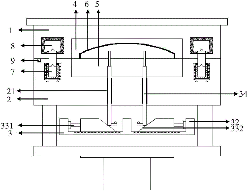
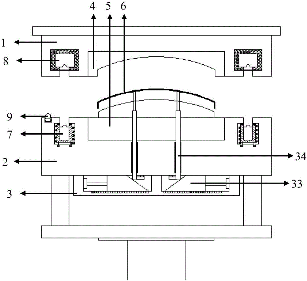
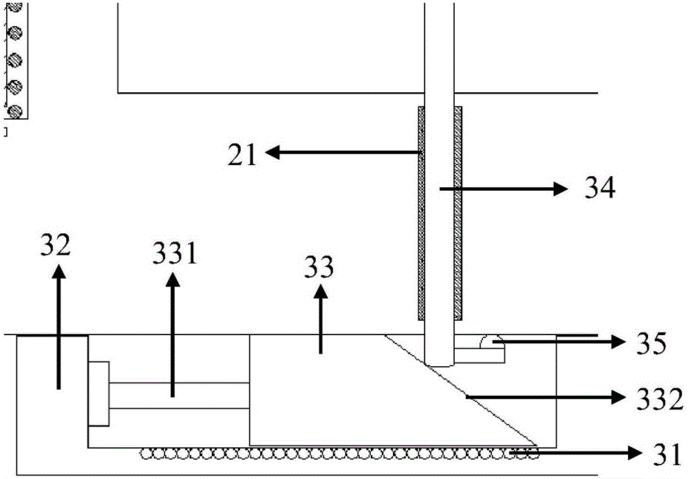
[0018] An embodiment of the inventive structure of the present invention is as Figure 1-5 As shown, it includes a fixed mold 1, a movable mold 2 and a top plate 3, and the fixed mold 1 and the movable mold 2 are respectively provided with a fixed mold kernel 4 and a movable mold kernel 5, and the fixed mold kernel 4 and the movable mold kernel 5 are in the After the mold is closed, a molding space for the product 6 to be molded can be formed; the top plate 3 is located in the middle of the movable mold 2 and fixedly arranged relative to the fixed mold 1, and at least one core-pulling slider is slid and fixed inside the top plate 3 33, the outer side of the core-pulling slider 33 is fixedly connected with the telescopic rod of the cylinder 331, and the inner side of the core-pulling slider 33 is a slope 332; each of the core-pulling sliders 33 is provided with There is at lea...


PUM


Abstract

The invention provides an injection mold. The injection mold comprises a fixed mold, a movable mold, a top plate, a fixed mold core and a movable mold core, wherein the top plate and the fixed mold are relatively fixed; core pulling sliding blocks are fixed inside the top plate; the core pulling sliding blocks are connected with cylinders; the inner sides of the core pulling sliding blocks are inclined planes; at least one ejector rod is arranged on each inclined plane; and ejection channels for allowing the ejector rods to perform reciprocating motion in the vertical direction are arranged inside the fixed mold and the movable mold. According to the injection mold, a product can be stably demolded more quickly.

Description

technical field [0001] The invention creates the technical field of mold processing and manufacturing, and in particular relates to an injection mold for cylinder core pulling and ejection. Background technique [0002] After the injection molding of the mold is completed, it is generally necessary to use an ejector mechanism including an ejector rod to eject the formed product during the mold opening process, so that the product can be completely separated from the mold. The ejection process of the existing ejection mechanism is generally carried out at a constant speed along with the mold opening process of the movable mold, the ejection effect is easily affected by the stroke of the movable mold, and the ejection effect is not good. In addition, since the ejector rod is prone to friction with the movable mold during the ejection process, the motion resistance is increased, the contact parts are easily worn, the service life of the equipment is reduced, and the production ...

Claims


Application Information

Patent Timeline
Patent Type & Authority Applications(China)
IPC IPC(8): B29C45/40B29C45/33B29C45/80B29C45/84
CPCB29C45/332B29C45/4005B29C45/80B29C45/84
Inventor 陈英跃杨斌李增祥陈磊张学荣张倩白文永
Owner TIANJIN CITY JIUYUE TECH
Why Eureka
Try Eureka