Liquid injection apparatus and method for driving the same

Inactive Publication Date: 2005-12-29
SEIKO EPSON CORP
View PDF15 Cites 27 Cited by
  • Summary
  • Abstract
  • Description
  • Claims
  • Application Information

AI Technical Summary

Benefits of technology

[0029] That is, by closing the second passage and applying the negative pressure to the nozzle surface of the liquid ejection head, the negative pressure can be accumulated on the liquid ejection head. In this state, by resuming the ink supply from the liquid reservoir chamber by opening the second passage, the liquid is rapidly discharged from the liquid ejection head. In this manner, ink with increased viscosity can be discharged from the nozzle

Problems solved by technology

Such an ink jet recording apparatus, when not being operated, often suffers an increase in viscosity of the ink in the nozzle and solidification of the ink because of evaporation of the ink solvent, such as water vapor and the like from the nozzle of the recording head.
As a result, there is the possibility of poor performance of the printing, such as dust deposition on the noz

Method used


Image

  • Liquid injection apparatus and method for driving the same
  • Liquid injection apparatus and method for driving the same
  • Liquid injection apparatus and method for driving the same

Examples


first embodiment

[0082] A first embodiment according to the present invention will be described below according to FIGS. 1 to 11.

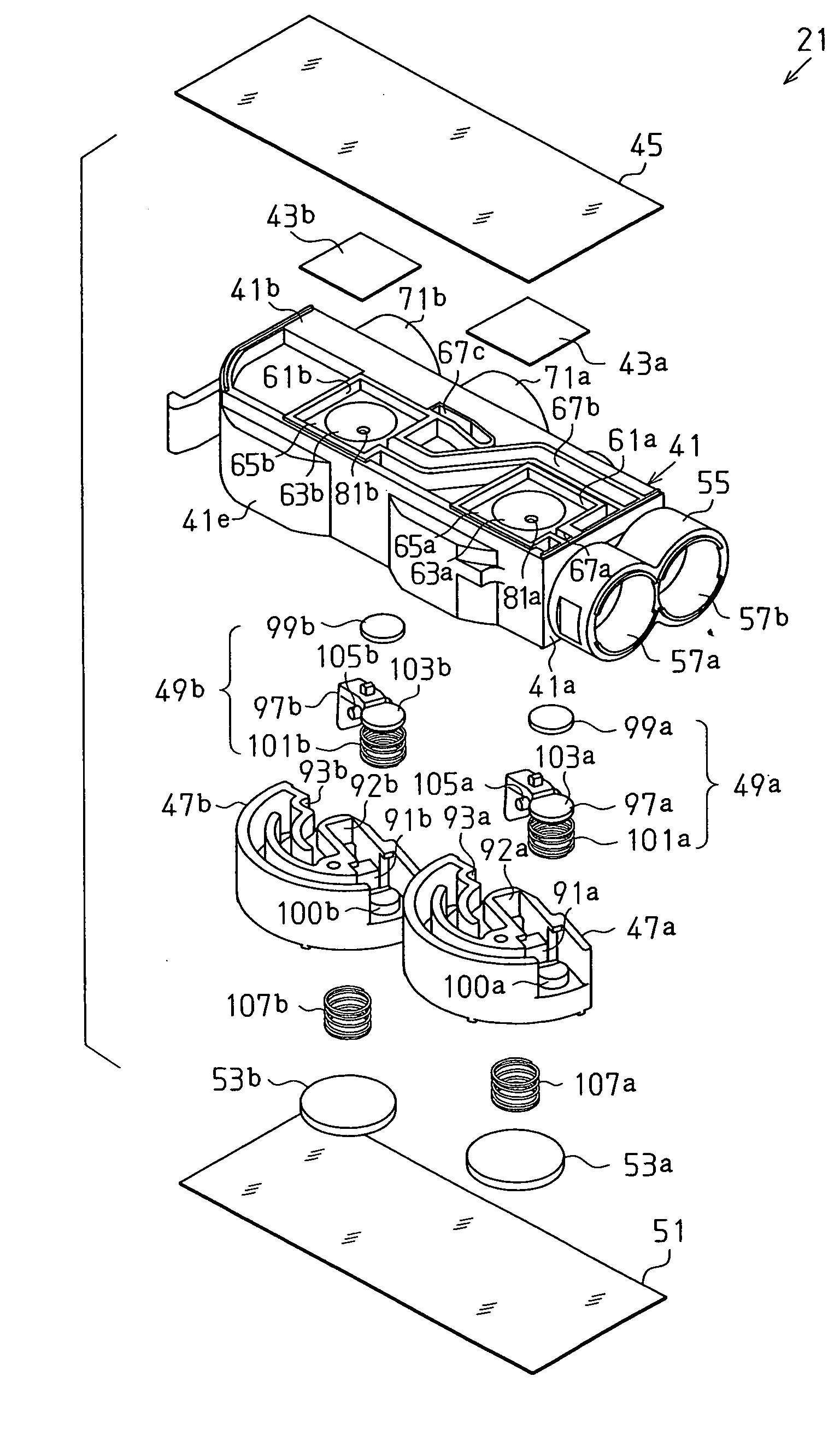
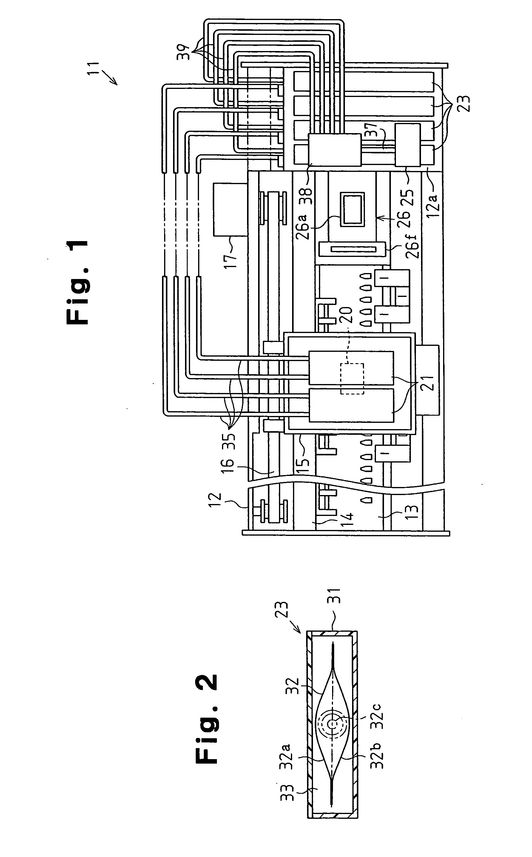
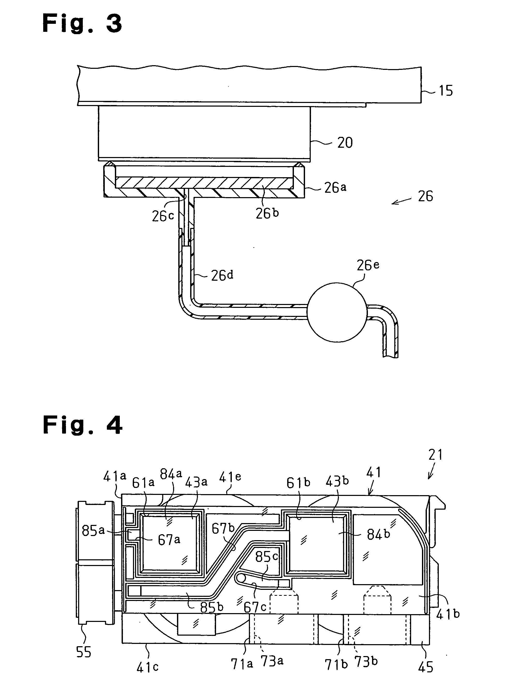
[0083] As shown in FIG. 1, an ink jet recording apparatus 11 as a liquid ejection apparatus of the present embodiment comprises a main body case 12, a platen 13, a guide shaft 14, a carriage 15, a timing belt 16, a carriage motor 17, and a recording head 20 as a liquid ejection head. Further, the ink jet recording apparatus 11 comprises a valve unit 21 as a liquid supply valve unit, an ink cartridge 23 as liquid reservoir means and a liquid cartridge, a pressure pump 25, and a capping device 26 as suction means.

[0084] The main body case 12 is a substantially rectangular case, and a cartridge holder 12a is formed in the right side end portion shown in FIG. 11. In the present embodiment, the longitudinal direction of the main body case 12 is taken as the main scanning direction.

[0085] The platen 13 is provided along the main scanning direction within the main body case 12...

second embodiment

[0178] Next, a second embodiment according to the present invention will be described according to FIGS. 12 to 18. Since the second embodiment is a constitution in which the valve unit alone of the first embodiment is changed, the detailed description of the components that are the same as those in the first embodiment will be omitted. FIG. 12 is a perspective view of an ink jet recording apparatus 145 as a liquid ejection apparatus, and FIG. 13 is an essential part perspective view of the ink jet recording apparatus 145.

[0179] As shown in FIG. 13, the ink jet recording apparatus 145 is provided with mutually opposing frame plates 145a and 145b at both sides thereof, and a guide shaft 146 is installed between the frame plates 145a and 145b. A carriage 147 is interposed relatively movable for a guide shaft 146, and is reciprocally movable in a main scanning direction by a carriage motor 17 (see FIG. 9). A recording medium P as a target is conveyed below a guide shaft 146 by an unill...

third embodiment

[0230] Next, a third embodiment according to the present invention will be described according to FIGS. 19 to 22. Since the third embodiment has a constitution in which the valve units or the ink introduction chambers of the first and second embodiments alone are changed, the description of the like parts will be omitted. FIG. 19 is a perspective view of a flow concentration path 220 constituting a liquid supply path, FIG. 20 is a top view of a main body 227 of a choke valve 221 connected to the flow concentration path 220, and FIG. 21 is an under surface view of the main body 227. FIG. 22 is an essential part cross-sectional view of the choke valve 221.

[0231] The flow concentration path 220 of the present embodiment has a constitution where the ink introduction chamber 178 shown in FIG. 16 alone is omitted from the flow concentration path 151 disclosed in the second embodiment. Consequently, the ink that has flowed into cylindrical interposal portions 222 provided in one side surf...


PUM


Abstract

A liquid ejection apparatus comprises a liquid cartridge for storing a liquid, a liquid ejection head for ejecting the liquid toward a target, a liquid supply path for guiding the liquid to the liquid ejection head from the liquid cartridge, and a capping device for drawing the liquid from the liquid ejection head. The liquid supply path comprises a plurality of wall surfaces, and a part of the wall surface is formed of a flexible member that is flexed by the inside-and-outside pressure difference of the liquid supply path. A pressure pump for adjusting the pressure of a fluid within the liquid supply path in the upstream side of the flexible member is provided.

Description

CROSS-REFERENCES TO RELATED APPLICATIONS [0001] This application is a continuation-in-part of prior copending patent application Ser. No. 10 / 871,611, filed Jun. 21, 2004.BACKGROUND OF THE INVENTION [0002] The present invention relates to a liquid ejection apparatus and a driving method thereof. [0003] Heretofore, in general, as a liquid ejection apparatus for ejecting a liquid from a nozzle toward a target, an ink jet recording apparatus has been widely used. This ink jet recording apparatus comprises a carriage and a recording head mounted on the carriage. While moving the carriage on the recording head, the apparatus ejects ink from the nozzle formed on the recording head and performs printing on a recording medium. [0004] Such an ink jet recording apparatus, when not being operated, often suffers an increase in viscosity of the ink in the nozzle and solidification of the ink because of evaporation of the ink solvent, such as water vapor and the like from the nozzle of the recordi...

Claims


Application Information

Patent Timeline
IPC IPC(8): B41J2/175B41J29/38
CPCB41J2/16532B41J29/38B41J2/17509B41J2/175
Inventor YOSHINO, KEIICHIROKUMAGAI, TOSHIOSEINO, TAKEOMORIKOSHI, KOJI
Owner SEIKO EPSON CORP
Why Eureka
Try Eureka