Paint mixer

a paint mixer and mixing machine technology, applied in the field of paint mixers, can solve the problems of not having a positive alignment between the center of the shaft and the center of the gear, and achieve the effect of simple and efficien

Active Publication Date: 2005-12-29
RED DEVIL EQUIP
View PDF19 Cites 34 Cited by
  • Summary
  • Abstract
  • Description
  • Claims
  • Application Information

AI Technical Summary

Benefits of technology

[0003] The present invention, in one aspect, is directed to a simple and efficient combined clamp and lock mechanism in which certain parts are used simultaneously to both clamp and lock and are useful in gyroscopic and platform or orbital mixers. In this aspect, an apparatus and method are provided in which a lead screw with a helical thread has at least on

Problems solved by technology

In another aspect, some prior art gyroscopic mixers had a rotating shaft projecting through a stationar

Method used


Image

  • Paint mixer
  • Paint mixer
  • Paint mixer

Examples


Embodiment Construction

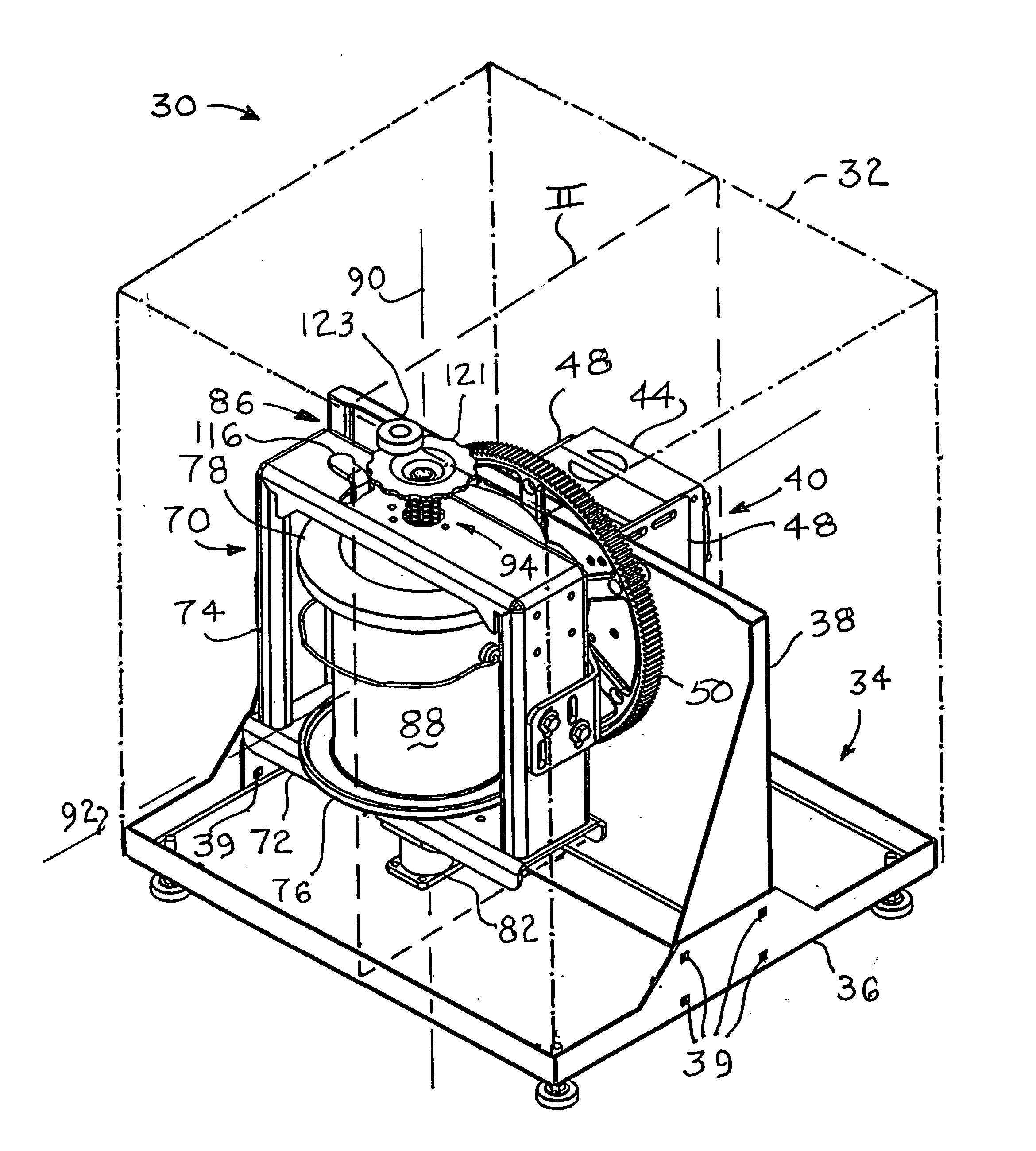
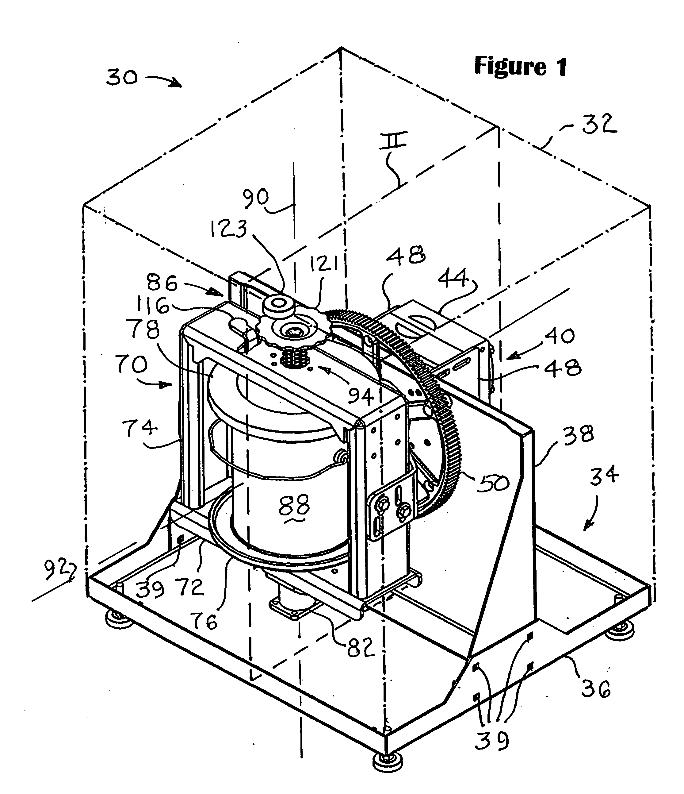
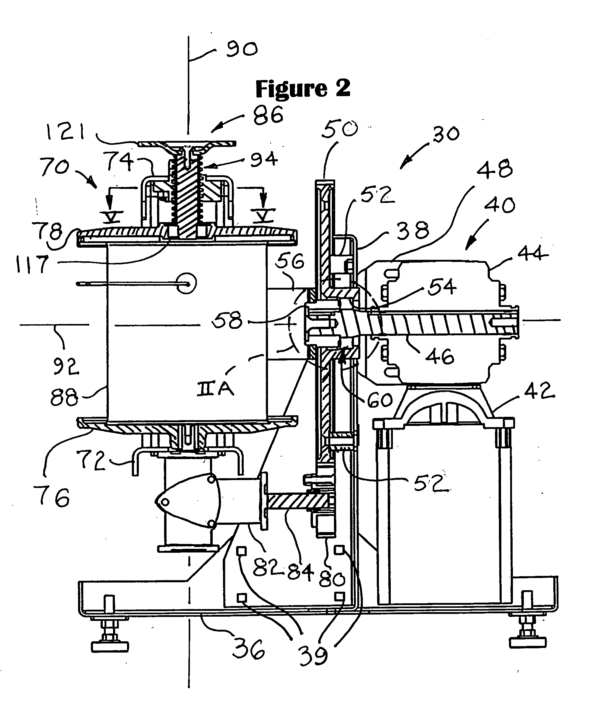
[0041] Referring to the Figures, and most particularly to FIGS. 1-4D, a paint mixer 30 useful in the practice of the present invention may be seen. As shown, mixer 30 is a gyroscopic type mixer that has a one gallon paint container capacity. However, it is to be understood that the present invention is also applicable to other sizes of gyro mixers (e.g., 5 gallon) and, in certain aspects, to platform mixers of various capacities. Mixer 30 is shown without an enclosure, however chain line 32 is used to indicate that preferably an enclosure is used to surround the mixer 30, but forms no part of the present invention. Mixer 30 is supported by a base 34 having a horizontal member 36 and a vertical member 38, each preferably formed of relatively rigid material, such as heavy gauge sheet metal. Members 36 and 38 may be secured together, for example, at locations 39 by conventional fastenings, such as machine screws or welding. A drive mechanism 40 is mounted to member 38 and includes an e...


PUM


Abstract

A gyroscopic paint mixer having a ratcheting lead screw paint container clamp and lock with a pawl releasably engaging an axial relief in the lead screw. A clamping frame is driven by a shaft maintained in concentricity with a stationary ring gear by an antifriction bearing mounted between the shaft and ring gear. A support plate has a peripheral lip forming a first recess sized to position either a generally square paint container or a generally D-shaped paint container. The support plate has a second recess to position a cylindrical paint container concentric to a spin axis.

Description

FIELD OF THE INVENTION [0001] This invention is in the field of paint mixing machines, particularly gyroscopic and platform or orbital mixers. BACKGROUND OF THE INVENTION [0002] In the past, paint mixers of the gyroscopic and platform types used various clamping mechanisms to secure the paint container in the mixer. Such mechanisms typically required an operator to advance or retract a clamping pad or plate with respect to one end of the paint container or containers held for mixing. Furthermore, to retain the paint contaner securely, the clamp mechanism requires a lock to prevent unintentional release or slippage of such clamping mechanisms. Such clamping and locking mechanisms often were constructed of a number of parts needing alignment for proper operation, due in part to the separation of functions between the clamping parts and the locking parts, which nevertheless were required to work together. The relatively large number of parts on occasion caused relatively high friction ...

Claims


Application Information

Patent Timeline
IPC IPC(8): B01F9/00B01F11/00B01F15/00B44D3/06
CPCB01F9/0001B01F2215/005B01F15/00753B01F15/0072B01F29/10B01F35/413B01F35/423B01F2101/30
Inventor MIDAS, THOMAS J.CURTIS, AARONHARROLD, BRENT THOMAS
Owner RED DEVIL EQUIP
Why Eureka
Try Eureka