Apparatus for electronic component mounting

Inactive Publication Date: 2005-12-29
PANASONIC CORP
View PDF9 Cites 3 Cited by
  • Summary
  • Abstract
  • Description
  • Claims
  • Application Information

AI Technical Summary

Benefits of technology

[0006] Consequently, the invention aims to provide an apparatus for electronic component mounting which can precisely identify an option device which was attached, and can certify authenticity thereof.
[0008] According to the invention, in the key code storage section which was attached to an option device, a key code, which shows that the option device is a legitimate product, is stored, and the key code is read out from the key code storage section in such a state that the option device was connected to the apparatus main body, and on the basis of the read key code, it is judged whether or not the option device is a legitimate option device which should be connected to the apparatus main body, and thereby, it is possible to precisely identify the option device which was attached and to certify authenticity thereof.

Problems solved by technology

However, in an apparatus market, we can not always say that only authentic devices are distributed, and there is such a case that imitation devices, which were copied illegally, are supplied.
The such like imitation device is imitated including the above-described identification mark, and therefore, it is not possible to precisely detect authenticity of a device which is used actually, by use of the device type detecting function which is shown in the above-described patent document example.
In this manner, in a conventional apparatus for electronic component mounting, there was such a problem that it is difficult to identify an option device precisely and to certify authenticity thereof.

Method used


Image

  • Apparatus for electronic component mounting
  • Apparatus for electronic component mounting
  • Apparatus for electronic component mounting

Examples


Embodiment Construction

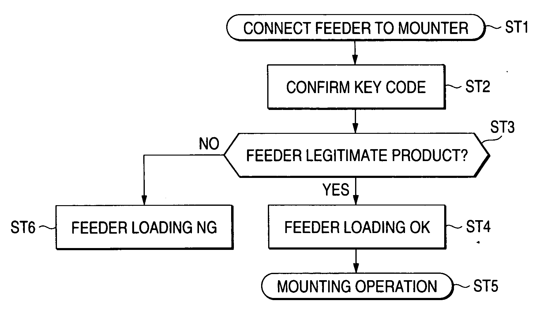
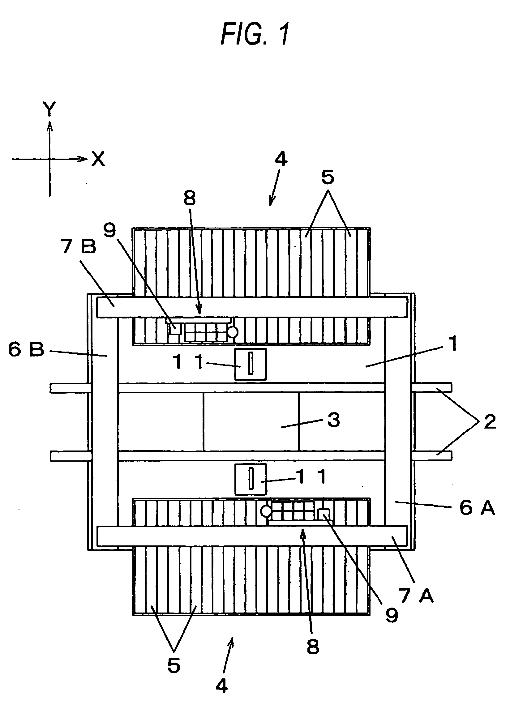
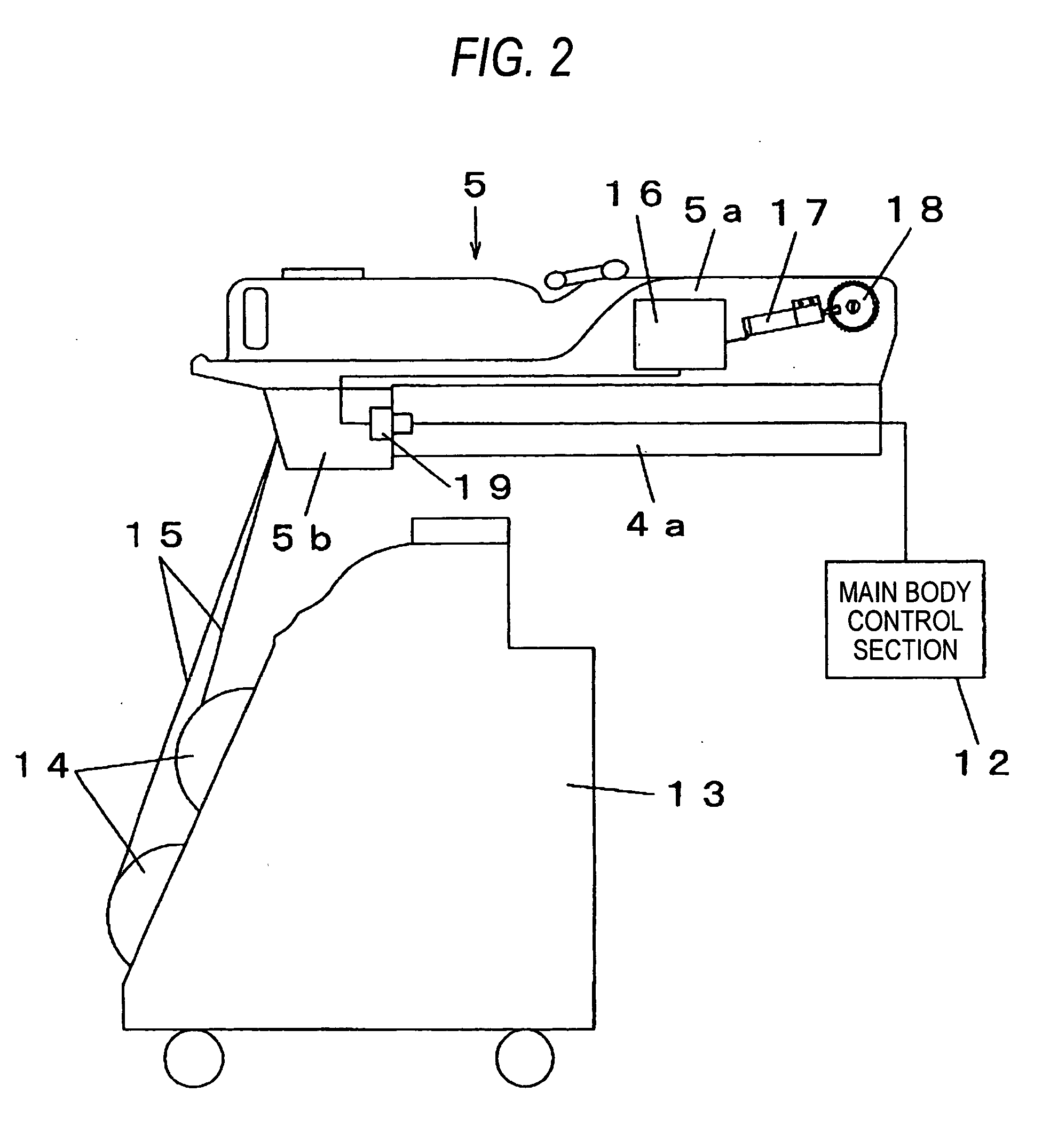
[0013] Next, an embodiment of the invention will be described with reference to drawings. FIG. 1 is a plan view of an electronic component loading apparatus of one embodiment of the invention, and FIG. 2 is a configuration explanation view of a component supply section in the electronic component loading apparatus of one embodiment of the invention, and FIG. 3 is a block diagram which shows a configuration of a control system of the electronic component loading apparatus of one embodiment of the invention, and FIG. 4 is a flow chart of a tape feeder attachment processing in the electronic component loading apparatus of one embodiment of the invention.

[0014] Firstly, with reference to FIG. 1, a configuration of the electronic component loading apparatus will be described. The electronic component loading apparatus is an apparatus for electronic component mounting which is used in an application for loading electronic components on a substrate to which solder printing was applied in ...


PUM


Abstract

An object is to provide an apparatus for electronic component mounting which can precisely identify an option device which was attached and can certify authenticity thereof. In a feeder 5 as an option device which is detachably attached to an electronic component loading apparatus which mounts electronic components on a substrate and used, a key code, which shows that the feeder 5 is a legitimate product, is stored in a key code storage section 16a which was disposed in a controller 16, and the key code is read out by a code reading section 12b from the key code storage section 16a in such a state that the feeder was connected to an apparatus main body, and the read key code is referred to data which was stored in a code data storage section 12a, and thereby, it is judged whether or not the feeder 5 is a legitimate product which should be connected to the apparatus main body.

Description

BACKGROUND OF THE INVENTION [0001] 1. Field of the Invention [0002] This invention relates to an apparatus for electronic component mounting which is used in an electronic component mounting line for mounting electronic components on a substrate. [0003] 2. Description of the Related Art [0004] An apparatus for electronic component mounting, which is used in an electronic component mounting line for mounting electronic components on a substrate, uses a number of option devices. For example, to an electronic component loading apparatus which mounts electronic components on a substrate, a parts feeder for supplying electronic components such as a tape feeder is attached according to types of components. As an apparatus to which plural kinds of the such like option devices are attached replaceably, one having a device type detecting function for automatically detecting what type of a device was attached has been known (e.g., see, JP-A-2001-135988 publication). An example, which is shown...

Claims


Application Information

Patent Timeline
IPC IPC(8): G03G15/00H05K13/04
CPCH05K13/0417H05K13/087
Inventor WADA, AKIFUMI
Owner PANASONIC CORP
Why Eureka
Try Eureka