Dental handpiece with improved grease retention

a technology of handpieces and grease, applied in the field of handpieces, can solve the problems of time-consuming and often difficult work, degrade the grease packing associated with the bearings of handpieces, etc., and achieve the effects of improving product quality, improving the efficiency of dental procedures, and improving the characteristics of grease retention

Inactive Publication Date: 2005-12-29
NOVAK EUGENE J +1
View PDF99 Cites 58 Cited by
  • Summary
  • Abstract
  • Description
  • Claims
  • Application Information

AI Technical Summary

Benefits of technology

[0005] A need exists therefore for a grease packed dental handpiece with improved grease retention characteristics. The handpiece should be improved with respect to the length of time and number of sterilization and use procedures that it can ...

Problems solved by technology

Such processes rapidly degrade the grease packing associated with the handpiece bear...

Method used


Image

  • Dental handpiece with improved grease retention
  • Dental handpiece with improved grease retention
  • Dental handpiece with improved grease retention

Examples


Embodiment Construction

[0017] The present invention has application to any dental handpiece where it is advantageous to provide for improved grease retention properties. Such properties are especially advantageous in dental handpieces that are subjected to repeated use and sterilization under harsh conditions of high heat and moisture. The present invention may therefore, find application in any handpiece driven by electric motor, pressurized air or the like.

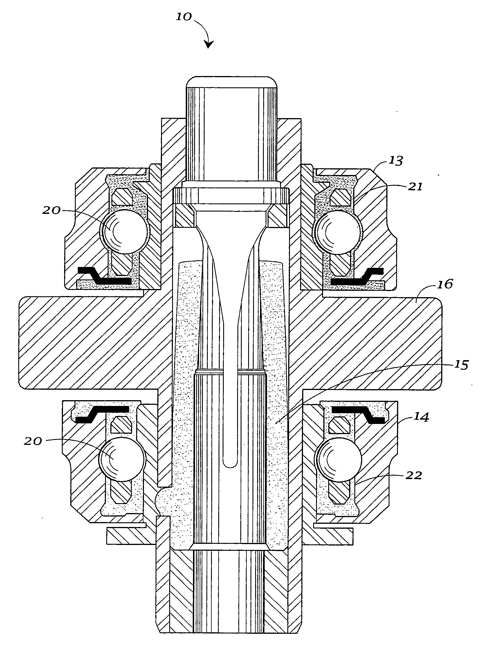
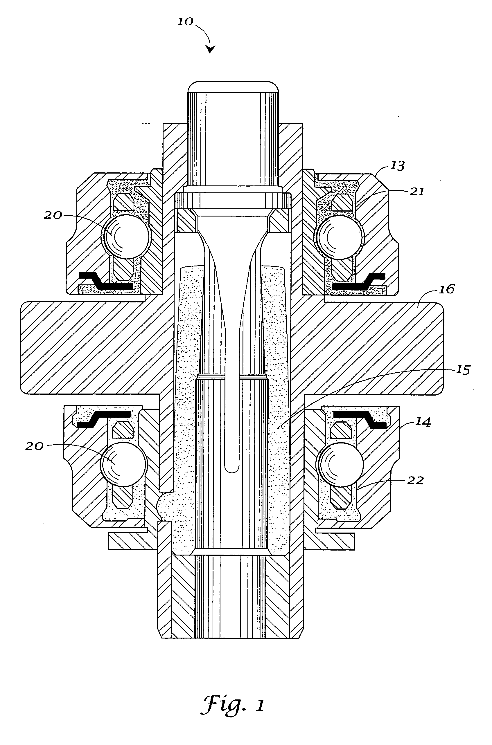
[0018] The handpiece selected for illustration is an air-driven handpiece 10 having a pair of ball bearing assemblies 13 and 14 supporting rotor 15 for rotation. The rotor includes any conventional driving means such as for example, an air-turbine 16 for rotatably driving rotor 15. The turbine depicted in FIG. 1 is a radial-flow turbine that is driven by air, but of course, can be of any conventional design.

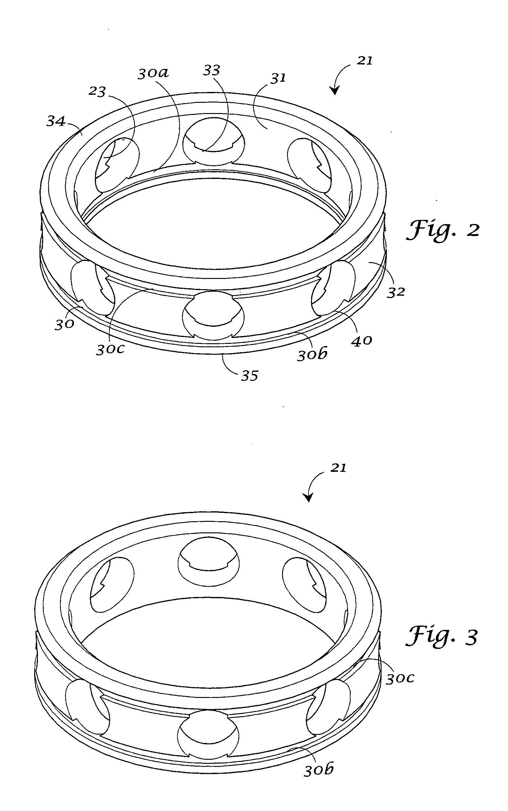
[0019] Bearing assemblies 13 and 14 are each provided with a plurality of balls 20 supported by annular retainers 21 and 22. The invention will ...


PUM


Abstract

A dental handpiece (10) has a rotor (15) and a ball bearing assembly (13, 14) supporting the rotor (15). At least one of the ball bearing assemblies (13, 14) has a ball (20) and a retainer (21). The retainer (21) has at least one grease retaining groove (30, 50) or void (51) therein.

Description

RELATED APPLICATIONS [0001] This application is a Continuation application of U.S. patent application Ser. No. 10 / 371,033 (Case MID-30D) filed Feb. 20, 2003, which claims the benefit from Provisional Application No. 60 / 359,962 filed Feb. 27, 2002.TECHNICAL FIELD [0002] The present invention is directed toward dental handpieces of the type employing greased bearings. More particularly, the invention is directed toward a dental handpiece having improved grease retention even with repeated exposure to conventional sterilization practices. The handpiece has at least one bearing retainer with a unique geometry of grease retention grooves. BACKGROUND OF THE INVENTION [0003] Dental handpieces of many types, including the air-driven type are known to have an outer housing which often includes a neck portion. Within the chamber of the housing is a rotor adapted to be driven by air supplied through the handle and neck. The housing often includes upper and lower openings that are axially align...

Claims


Application Information

Patent Timeline
IPC IPC(8): A61C1/14A61C1/18F01M11/04F16C33/38F16C33/66
CPCA61C1/14A61C1/181F01M11/0408F16C19/163F16C33/6614F16C2316/13F16C33/3843F16C33/767F16C19/547
Inventor NOVAK, EUGENE J.AYZENSHETYN, MIKHAIL
Owner NOVAK EUGENE J
Why Eureka
Try Eureka