
Implantable prosthesis having reinforced attachment sites

a technology of attachment sites and implants, which is applied in the field of composite multi-layer implantable grafts, can solve the problems of eptfe grafts being susceptible to tearing, flexible grafts creating undesirable stresses, and relatively non-compliant eptfe grafts, etc., and achieves the effect of strengthening attachment sites

Inactive Publication Date: 2005-12-29
LIFESHIELD SCI
View PDF70 Cites 55 Cited by
  • Summary
  • Abstract
  • Description
  • Claims
  • Application Information

AI Technical Summary

Problems solved by technology

Such flexibility may result from the stretching of the textile yarns forming the graft.
In other words, the graft flexibility may create undesirable stresses at the suture locations of the implanted graft.
Grafts formed of ePTFE tend to be relatively non-compliant as compared with textile grafts and natural vessels.
Further, while exhibiting a high degree of tensile strength, ePTFE grafts are susceptible to tearing.
Moreover, suture hole bleeding is a problem associated with conventional ePTFE grafts.
Thus, the ePTFE grafts lack many of the advantageous properties of certain textile grafts.
While using a vascular graft in conjunction with support structures offers certain benefits, it is also known that support structures such as a stent can result in axial elongation and radial shrinkage of the graft material due to the stresses applied to the graft material by the support structure during the contraction and expansion of the support structure.
In such embodiments, one of the primary failure modes of stent grafts is the loss of covering integrity at suture attachment sites.
Depending on the strength of the base material the holes may elongate to a point whereby the device may lose integrity.

Method used


Image

  • Implantable prosthesis having reinforced attachment sites
  • Implantable prosthesis having reinforced attachment sites
  • Implantable prosthesis having reinforced attachment sites

Examples


Embodiment Construction

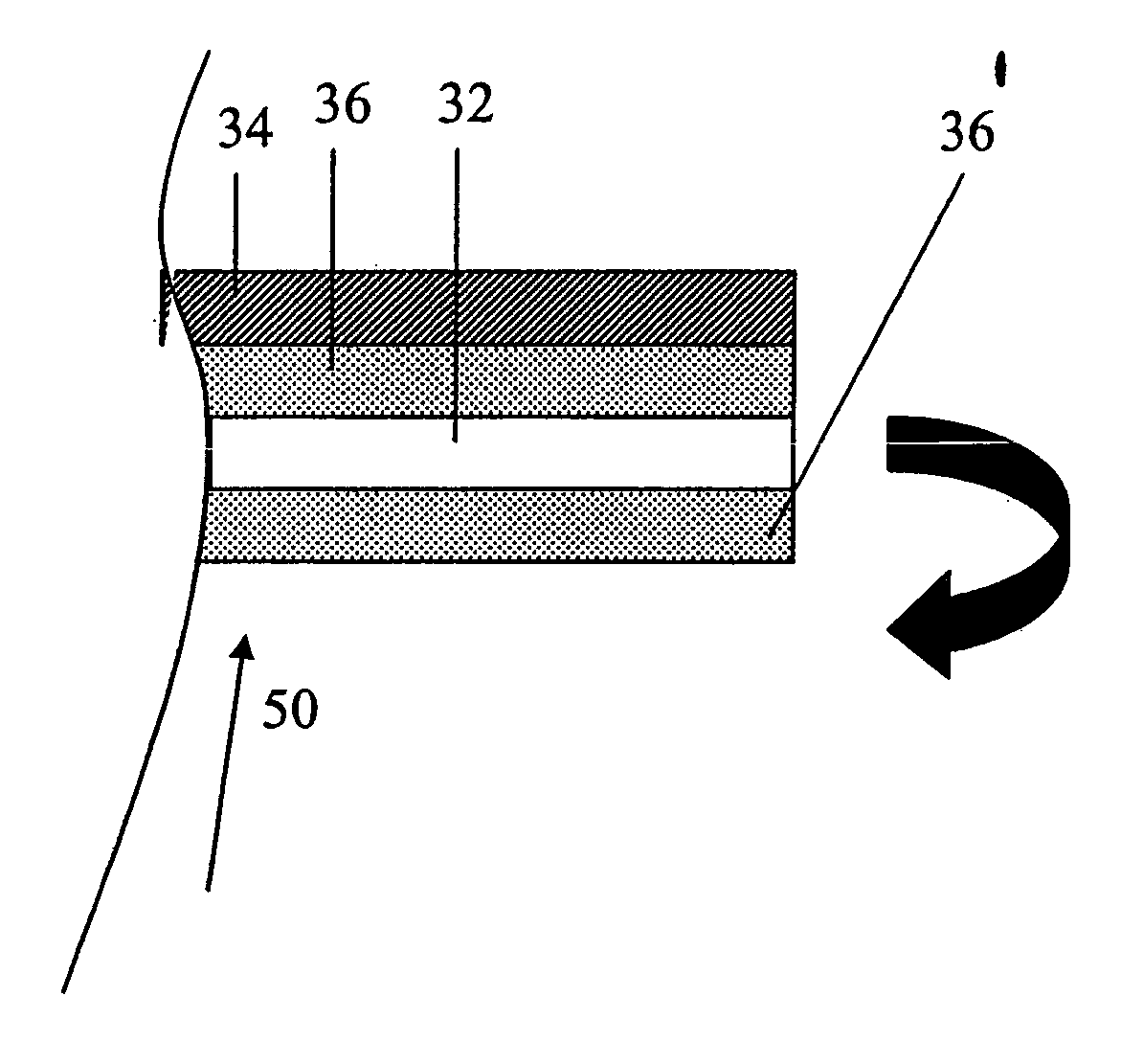
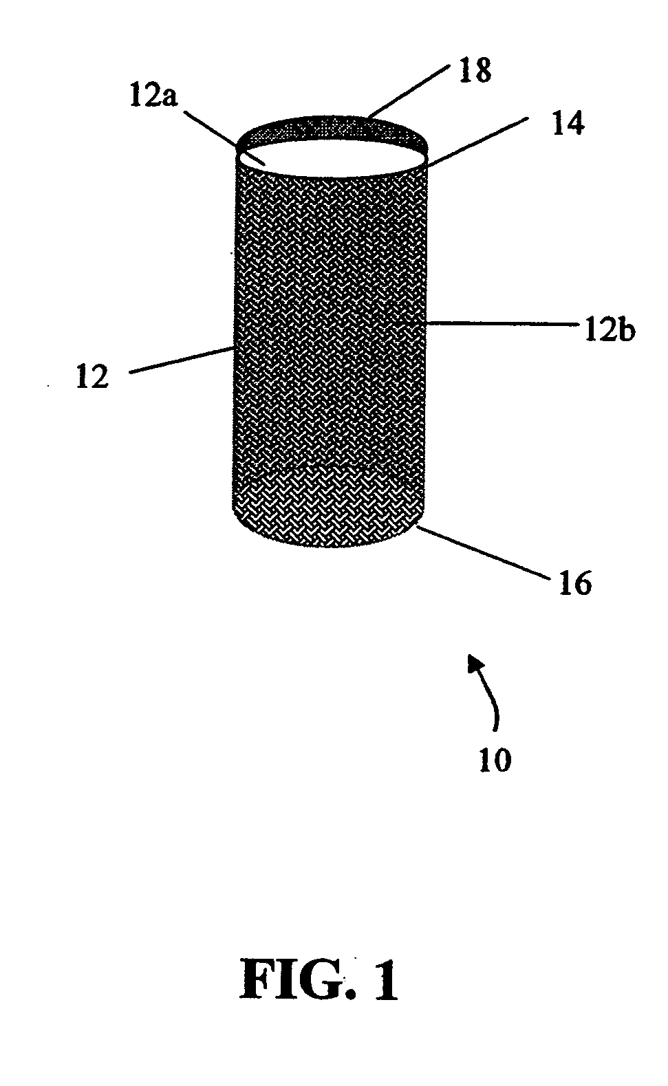
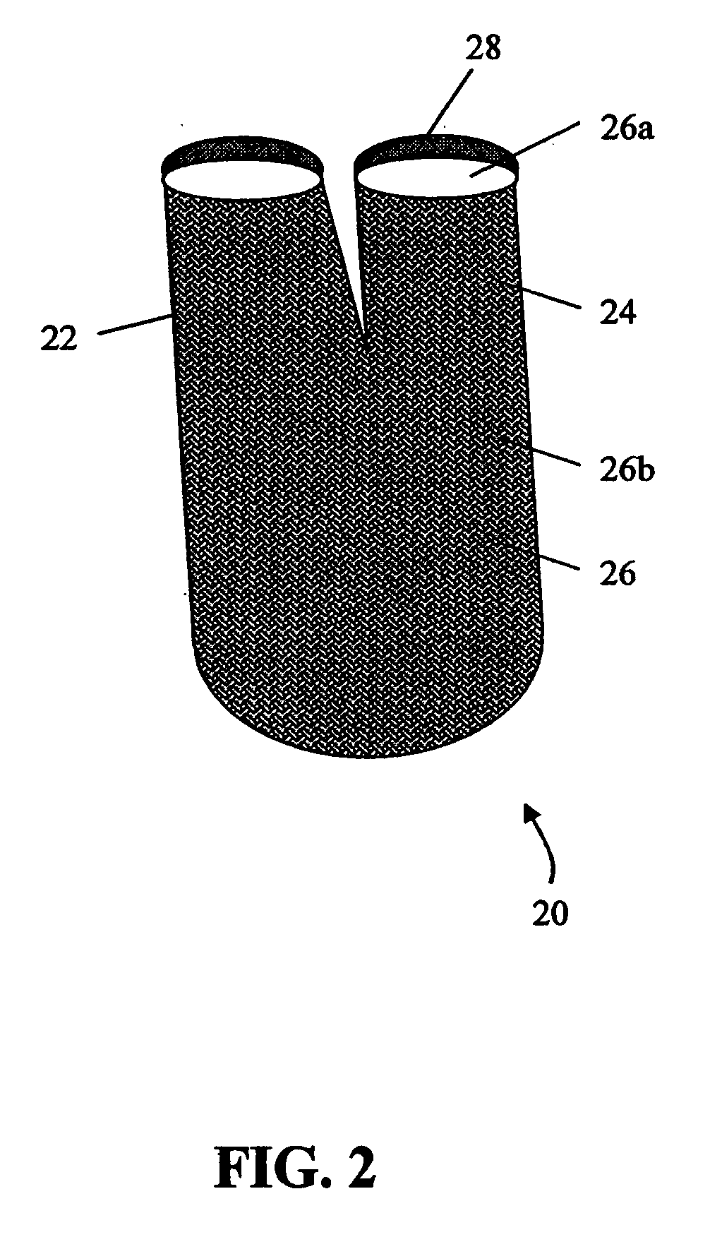
[0022] One aspect of the present invention relates to an implantable medical device including an elongate tubular graft and a reinforcement member for establishing a reinforced attachment site for preferably attaching the graft to a stent. In one desired embodiment, the reinforcement member is located at each of the two opposing graft ends for reinforcing the attachment sites of graft or hybrid graft materials that are used as stent-graft coverings. The graft including the reinforcement member can be an ePTFE graft, textile graft, or a hybrid graft. For example, in one desired embodiment, the reinforced graft is a hybrid graft including an inner ePTFE layer and an outer textile layer. The hybrid graft layers can be secured together, preferably by an elastomeric bonding agent. The prosthesis of the present invention may include ePTFE-lined textile grafts, and ePTFE grafts including a textile covering.

[0023] While this invention is satisfied by embodiments in many different forms, th...


PUM


Abstract

The present invention provides an implantable graft that includes an elongate graft tube having opposing ends defining an attachment site for attaching the graft to a stent. The graft further includes a reinforcement member attached adjacent to at least one of the ends of the graft for establishing a reinforced attachment site for the graft, thereby preventing elongation of a suture hole in the material. Furthermore, the present invention provides a graft wherein at least one end of the graft is folded over itself and glued or sutured to itself and / or the stent, thereby forming a reinforcement thereto.

Description

FIELD OF INVENTION [0001] The present invention relates generally to a implantable prosthesis material and structure. More particularly, the present invention relates to a composite multilayer implantable graft having a tubular structure with ends of the graft defining an attachment site for attaching the graft to a stent and a reinforced member for establishing a reinforced attachment site for the prosthesis. BACKGROUND OF RELATED TECHNOLOGY [0002] Implantable prostheses are commonly used in medical applications. One of the more common prosthetic structures is a tubular prosthesis which may be used as a vascular graft to replace or repair or otherwise correct a damaged or diseased blood vessel. To maximize the effectiveness of such a prosthesis, it should be designed with characteristics which closely resemble that of the natural body lumen which it is repairing or replacing. [0003] One form of a conventional tubular prosthesis specifically used for vascular grafts includes a texti...

Claims


Application Information

Patent Timeline
Patent Type & Authority Applications(United States)
IPC IPC(8): A61F2/06
CPCA61F2/07A61F2002/072A61F2002/075A61F2220/0075A61F2220/005A61F2220/0058A61F2210/0076
Inventor KUJAWSKI, DENNISRAKOS, RONALDSOWINSKI, KRZYSZTOFDONG, JERRY Q.
Owner LIFESHIELD SCI
Learn More