Trace analyzing apparatus, trace analyzing method, and processor

a trace analysis and trace analysis technology, applied in the field of trace analysis apparatus and trace analysis method, can solve the problems of inability to capture a signal for analysis, inability to store units of variable length data in that memory without, and useless data entering in the vacant area

Active Publication Date: 2005-12-29
KK TOSHIBA
View PDF14 Cites 39 Cited by
  • Summary
  • Abstract
  • Description
  • Claims
  • Application Information

AI Technical Summary

Problems solved by technology

Development of higher-speed processors makes it difficult to capture a signal for analysis.
However, there is a disadvantage in that when storing trace information of this variable length trace storage format in a memory (trace memory), units of variable length data cannot be stored in that memory without leaving vacant areas in the memory.
Consequently, useless data is entered in the vacant areas.
Therefore, 1 / 16 of the trace memory capacity cannot be used for storing trace information.
Furthermore, the start addresses of respective pieces of trace information, each indicated by that 4-bit information, are at 4-bit intervals, and when the end address of the immediately preceding trace information is not multiples of 4 minus 1, useless data is entered, preventing storage of a maximum amount of trace information in the memory.

Method used


Image

  • Trace analyzing apparatus, trace analyzing method, and processor
  • Trace analyzing apparatus, trace analyzing method, and processor
  • Trace analyzing apparatus, trace analyzing method, and processor

Examples


embodiment

(Overall Structure)

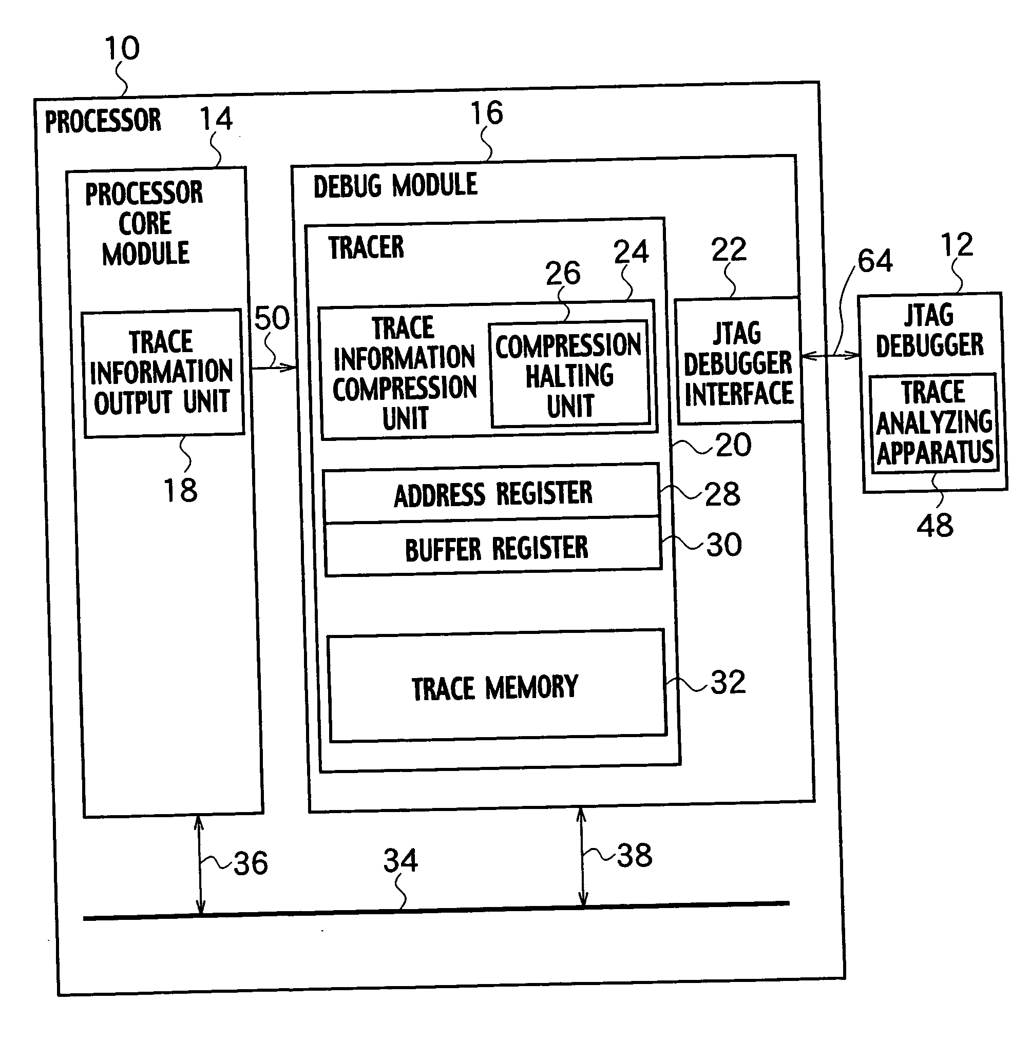
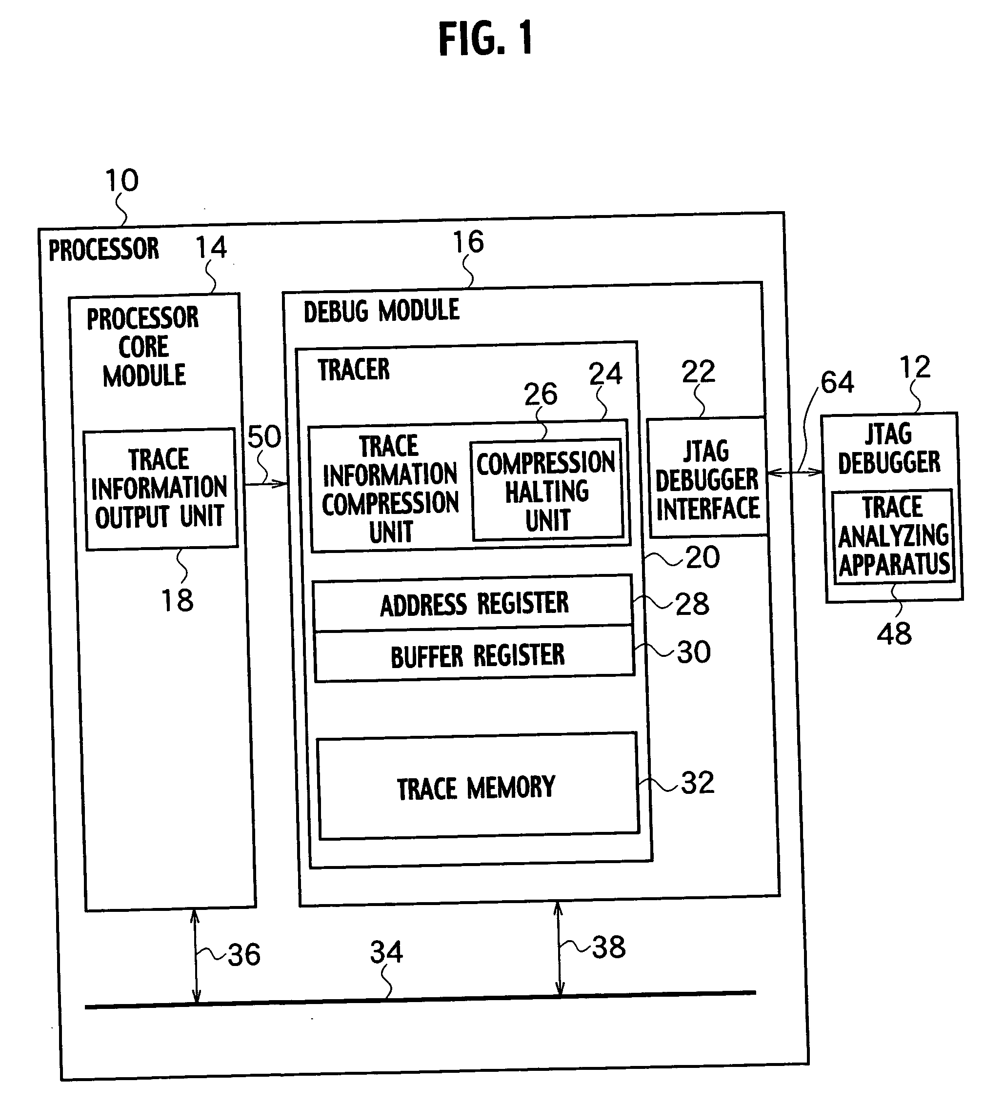
[0029] An overall schematic block diagram of a trace analyzing apparatus 48 embedded JTAG debugger 12 and a processor 10 to be analyzed, according to the embodiment of the present invention, is shown in FIG. 1.

[0030] As shown in FIG. 1, the processor 10, according to the embodiment of the present invention, includes: a processor core module 14, which includes a trace information output unit 18; the tracer 20; a debug module 16, which includes a JTAG debugger interface 22; and a main bus 34, which connects between the processor core module 14 and the debug module 16 via buses 36 and 38.

[0031] The processor core module 14 reads in and executes processor instructions. The debug module 16 is connected to the external JTAG debugger 12 via the JTAG debugger interface 22 and a JTAG debug output bus 64, and is controllable by the external JTAG debugger 12 when in a debugging process.

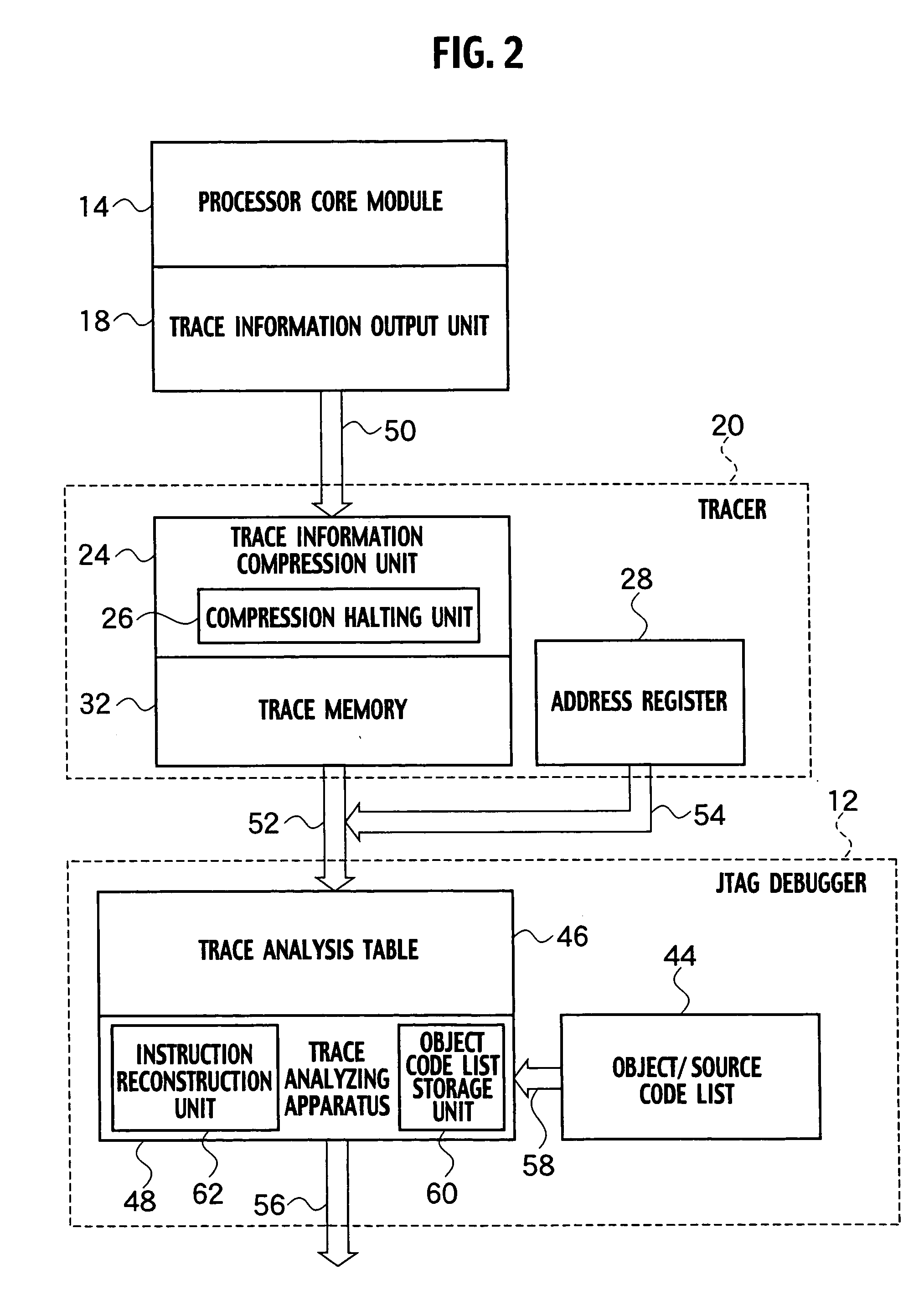
[0032] The trace information output unit 18 in the processor core module 14 is connec...


PUM


Abstract

A trace analyzing apparatus, which includes a trace analysis table, an instruction reconstruction unit that reconstructs and sends an execution address and an instruction code of trace information, and an object code list storage unit, reads out an object code list and trace information, captures each piece of information in reverse order from the last stored address information stored in an address register, and then registers them in the trace analysis table.

Description

CROSS REFERENCE TO RELATED APPLICATIONS AND INCORPORATION BY REFERENCE [0001] This application is based upon and claims the benefit of priority from prior Japanese Patent Application P2004-191661 filed on Jun. 29, 2004; the entire contents of which are incorporated by reference herein. BACKGROUND OF THE INVENTION [0002] 1. Field of the Invention [0003] The present invention relates to a trace analyzing apparatus and a trace analyzing method. More specifically, it relates to a trace analyzing apparatus, a trace analyzing method, and a processor, which analyze trace information stored in a trace memory and allows display of the dynamic program execution status of the processor. [0004] 2. Description of the Related Art [0005] Recent microprocessors have been required not only to provide a higher operating performance at a higher operating frequency, but also to support a decrease in the development time of a processor embedded system. In development of a processor or a processor embedd...

Claims


Application Information

Patent Timeline
Patent Type & Authority Applications(United States)
IPC IPC(8): G06F11/00
CPCG06F11/3636
Inventor KIMURA, KATSUYUKI
Owner KK TOSHIBA
Why Eureka
Try Eureka