More specifically, it concerns the transmission of video data over networks that are prone to error.
The storage space required for raw multimedia data is huge, typically many megabytes.
Because of the relatively fast
frame rate, images in consecutive frames tend to be quite similar and thus contain a considerable amount of redundant information.
In many cases, this means that the overall change between one video frame and the next is rather small.
Sufficiently efficient compression cannot usually be achieved by simply reducing the various forms of redundancy in a given sequence of images.
Thus, most current video encoders also reduce the quality of those parts of the
video sequence which are subjectively the least important.
In the
INTER frame case, the predicted (motion-compensated) image is rarely precise enough, and therefore a spatially compressed prediction error image is also associated with each
INTER frame.
It should be noted that while B-pictures may improve compression performance when compared with P-pictures, they require more memory for their construction, their
processing requirements are more complex, and their use introduces additional delays.
It should be apparent from the above discussion of temporal prediction that the effects of
data loss, leading to the corruption of
image content in a given frame, will propagate in time, causing corruption of subsequent frames predicted from that frame.
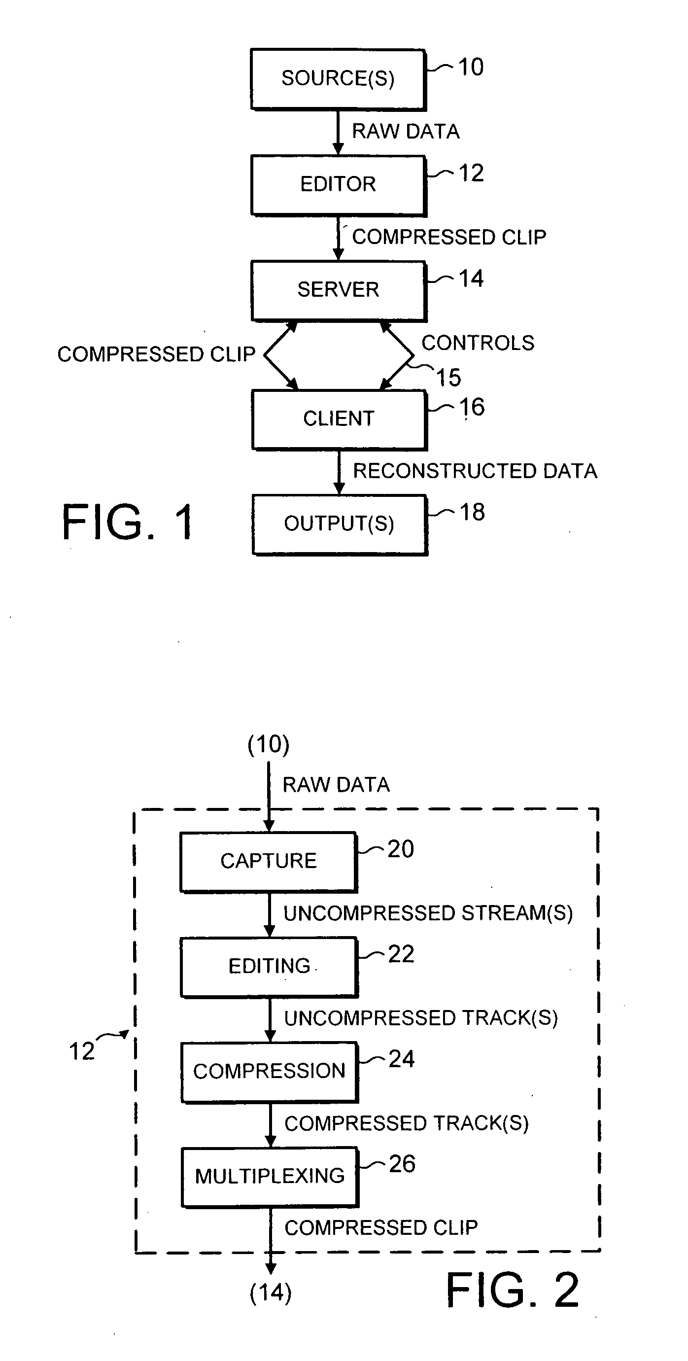
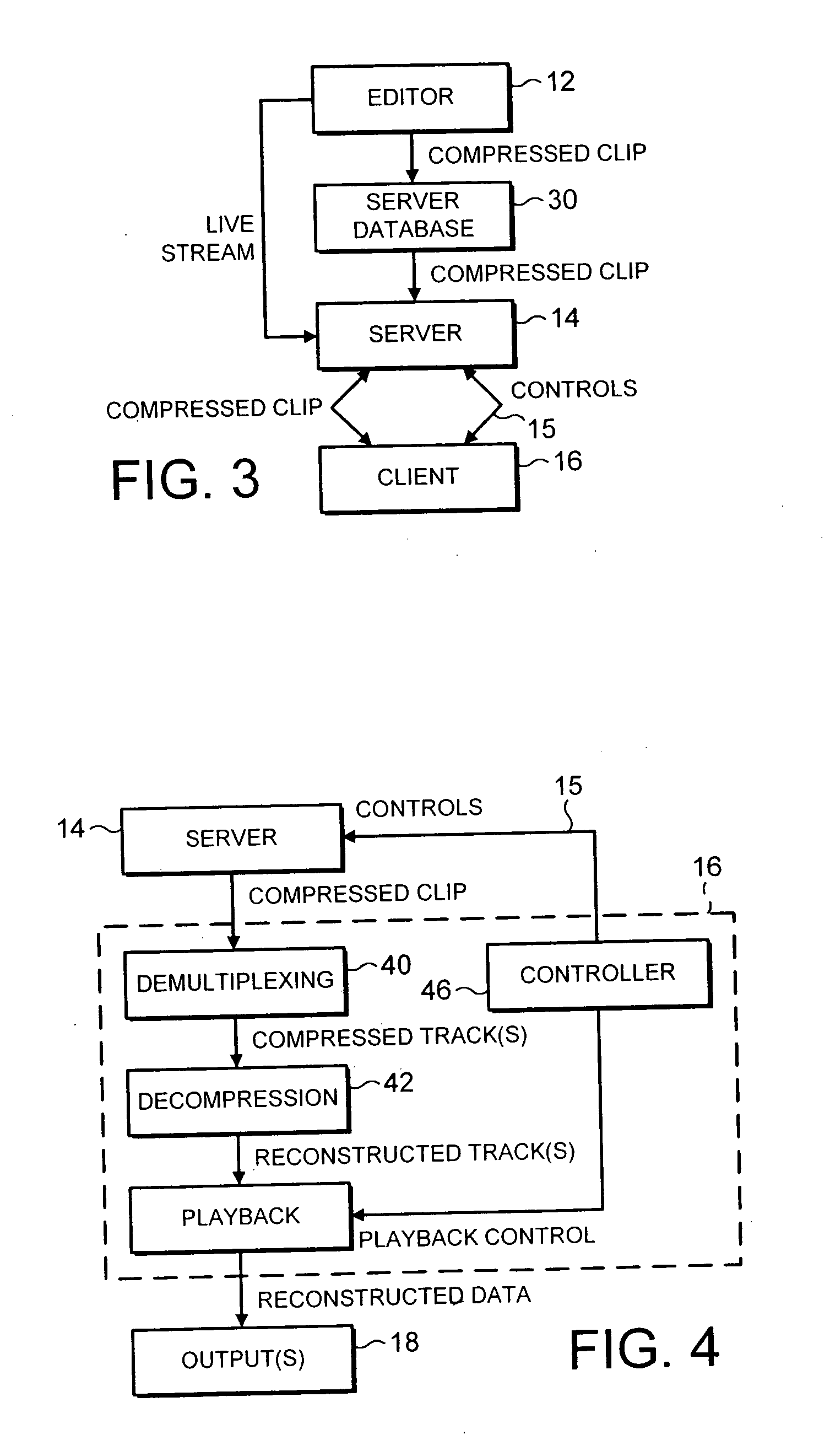
In the light of the information provided above concerning the nature of currently known multimedia retrieval systems and video coding (compression) techniques, it should be appreciated that a significant problem may arise in the retrieval / streaming of video sequences over communications networks.
Because video frames are typically predicted one from the other, compressed video sequences are particularly prone to
transmission errors.
If data loss occurs due to a network transmission error, information about the content of the video
stream will be lost.
If information vital to reconstruction of a video frame is lost (e.g. information stored in a picture header), it may not be possible to display the image at the receiving
client.
Thus, the entire frame and any sequence of frames predicted from it are lost (i.e. cannot be reconstructed and displayed).
However, frames predicted from the corrupted frame are still affected and the error propagates both temporally and spatially within the
image sequence until the next INTRA frame is transmitted and correctly reconstructed.
This is a particularly severe problem in very low bit-rate communications, where INTRA frames may be transmitted only infrequently (e.g. one INTRA frame every 10 seconds).
In circuit switched networks, such as fixed line and mobile telephone systems,
transmission errors generally take the form of bit reversals.
In other words, the
digital data representing e.g. the video content of a multimedia
stream, is corrupted in such a manner that l's are turned into O's and vice versa, leading to misrepresentation of the
image content.
In mobile telephone networks, bit reversal errors typically arise as a result of a decrease in the quality of the radio link.
In this kind of network, data packets are usually lost as a result of congestion in the network.
If the network becomes congested, network elements, such as gateway routers, may discard data packets and, if an unreliable transport protocol such as UDP (
User Datagram Protocol) is used, lost packets are not retransmitted.
Normally, the majority of video frames are temporally predicted INTER frames and thus the loss of one or more such pictures has serious consequences for the quality of the video sequence as reconstructed at the
client terminal.
Not only may one or more frames be lost, but all subsequent images predicted from those frames will be corrupted.
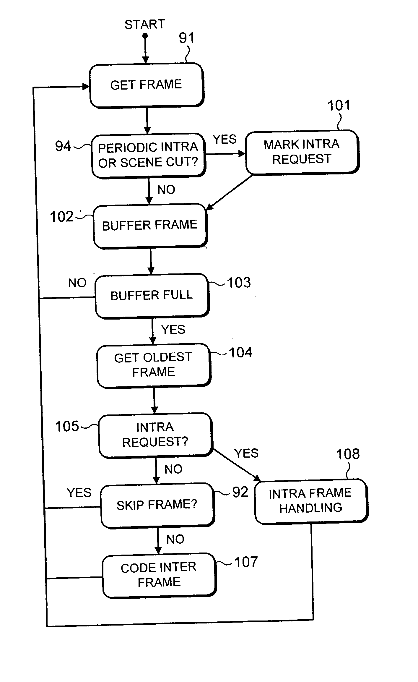
Error concealment refers to the capability to conceal the effects of transmission errors so that they should be hardly visible in the reconstructed video.
If a video sequence contains a long
train of INTER frames, loss of image data as a result of transmission errors will lead to corruption of all subsequently decoded INTER frames and the error will propagate and be visible for a long time in the decoded video
stream.
This is an undesirable effect, particularly in low bit-rate transmission channels or in channels where the total available bandwidth must be shared between a multiplicity of users.
In the light of the arguments presented above, concerning the nature of multi-media retrieval systems and compressed video sequences, it will be appreciated that there exists a significant problem relating to limiting the effect of transmission errors on perceived
image quality.
While some prior art methods address this problem by limiting the prediction
path length used in compressed video sequences, in the majority of cases, their use results in an increase in the bit-rate required to code the sequence.

