Stabilization of a hydroformylation process

a hydroformylation process and hydroformylation technology, applied in the direction of carbonyl compound preparation, liquid degasification, separation processes, etc., can solve the problems of loss of catalyst or catalytic activity, decrease in catalyst productivity, increase in production costs of aldehyde products, etc., to prevent and/or lessen the cycling of process parameters, reduce the cost of catalyst production, and stabilize reaction rate and process parameters

Active Publication Date: 2008-11-04
DOW TECH INVESTMENTS
View PDF46 Cites 44 Cited by
  • Summary
  • Abstract
  • Description
  • Claims
  • Application Information

AI Technical Summary

Benefits of technology

[0026]The novel hydroformylation process invention described hereinabove effectively controls sudden changes and / or cycling of process parameters and provides for process stability while operating under conditions wherein the hydroformylation reaction rate is negative or inverse order in carbon monoxide, such that reaction rate decreases as carbon monoxide partial pressure increases and reaction rate increases as carbon monoxide partial pressure decreases. In a novel aspect and in contrast to the prior art, this invention allows for fluctuation or floating of the carbon monoxide partial pressure up and down, such that reaction rate can be quenched or accelerated, as desired, to stabilize reaction rate and process parameters. Beneficially, the process of this invention achieves this reaction stability and prevents and / or lessens cycling of process parameters in a simple and cost effective fashion by eliminating the need for large and costly heat exchangers employed in the prior art. Moreover, as compared with the prior art, the process of this invention advantageously provides for improved and more rapid recovery from sudden and extreme process deviations. With stable operation in the negative or inverse order region of the rate curve, catalyst lifetime is beneficially enhanced by minimizing the detrimental effects of poisoning or inhibiting phosphorus ligand byproducts. As a further advantage, the process of this invention allows for operation in the inverse order region at carbon monoxide partial pressures nearer to the peak of the Hydroformylation Rate versus Carbon Monoxide Partial Pressure curve (illustrated hereinafter), which beneficially provides for higher hydroformylation reaction rates and / or catalyst productivity and higher normal to branched product ratios. No need exists to overfeed carbon monoxide to the process, which is kinetically controlled. Kinetic control, which leads to higher reaction rates, is more preferable than present-day mass transfer methods of process control. Advantageously, the process of this invention also provides for reduced alkane formation and reduced olefin isomerization, both features increasing the efficient use of olefin reactant. Finally, the process of this invention provides a method for determining, for any selected organopolyphosphite ligand, the optimal range of carbon monoxide partial pressures within the inverse order region of the rate curve and provides a method for stable operation within this range.

Problems solved by technology

Loss of catalyst or catalytic activity due to undesirable side-reactions of the expensive rhodium catalysts can be detrimental to the production of the desired aldehyde.
Production costs of the aldehyde product increase when the productivity of the catalyst decreases.
All such hydrolysis reactions, however, invariably produce acidic phosphorus compounds that further catalyze the hydrolysis reactions.
Thus, the eventual build-up of unacceptable amounts of such poisoning and inhibiting materials causes the destruction of the organopolyphosphite ligand, thereby rendering the hydroformylation catalyst ineffective (deactivated) and the valuable rhodium metal susceptible to loss; such as, by precipitation and / or depositing on the walls of the reactor.
Higher carbon monoxide partial pressures give both higher catalytic activity and lower efficiency losses to alkanes.
Nevertheless, operation of the hydroformylation process in the negative or inverse order region of the rate curve with respect to carbon monoxide presents problems, which are not typically seen on the positive order side of the rate curve.
More specifically, when the hydroformylation process is positive order in carbon monoxide, an increase in reaction rate consumes carbon monoxide, which leads consequentially to a decrease in carbon monoxide partial pressure.
In a batch process, a feedback loop develops that can result in essentially rapid and complete consumption of the limiting reactant and termination of the hydroformylation process.
Cycling disadvantageously disrupts steady operation.
Thus, when operating in the negative order region of the rate curve, although the detrimental effects of inhibiting phosphorus byproducts can be reversed or reduced, the hydroformylation process itself becomes more difficult to stabilize and control.
Moreover, operation under negative order conditions generally necessitates operation at high carbon monoxide partial pressures well away from the peak of the Hydroformylation Rate versus Carbon Monoxide Partial Pressure curve.
The disclosed method requires controlling the differential between a reaction product effluent temperature and a heat exchanger's coolant temperature to less than about 25° C. Disadvantageously, this prior art method requires large and costly heat exchangers.
Also, due to the large thermal load of the reaction fluid, the time constant for recovery from a sudden temperature deviation may be unacceptably slow.
Disadvantageously, the disclosed process is not suitably adapted for hydroformylation processes that employ hydrolysable organophosphorus ligands and therefore prefer operation in the negative or inverse order region of the rate curve.
Disadvantageously, the disclosed process is not suitably adapted to hydroformylation processes that employ hydrolysable organophosphorus ligands and therefore prefer operation in the negative or inverse order region of the rate curve.

Method used


Image

  • Stabilization of a hydroformylation process
  • Stabilization of a hydroformylation process
  • Stabilization of a hydroformylation process

Examples


example 1

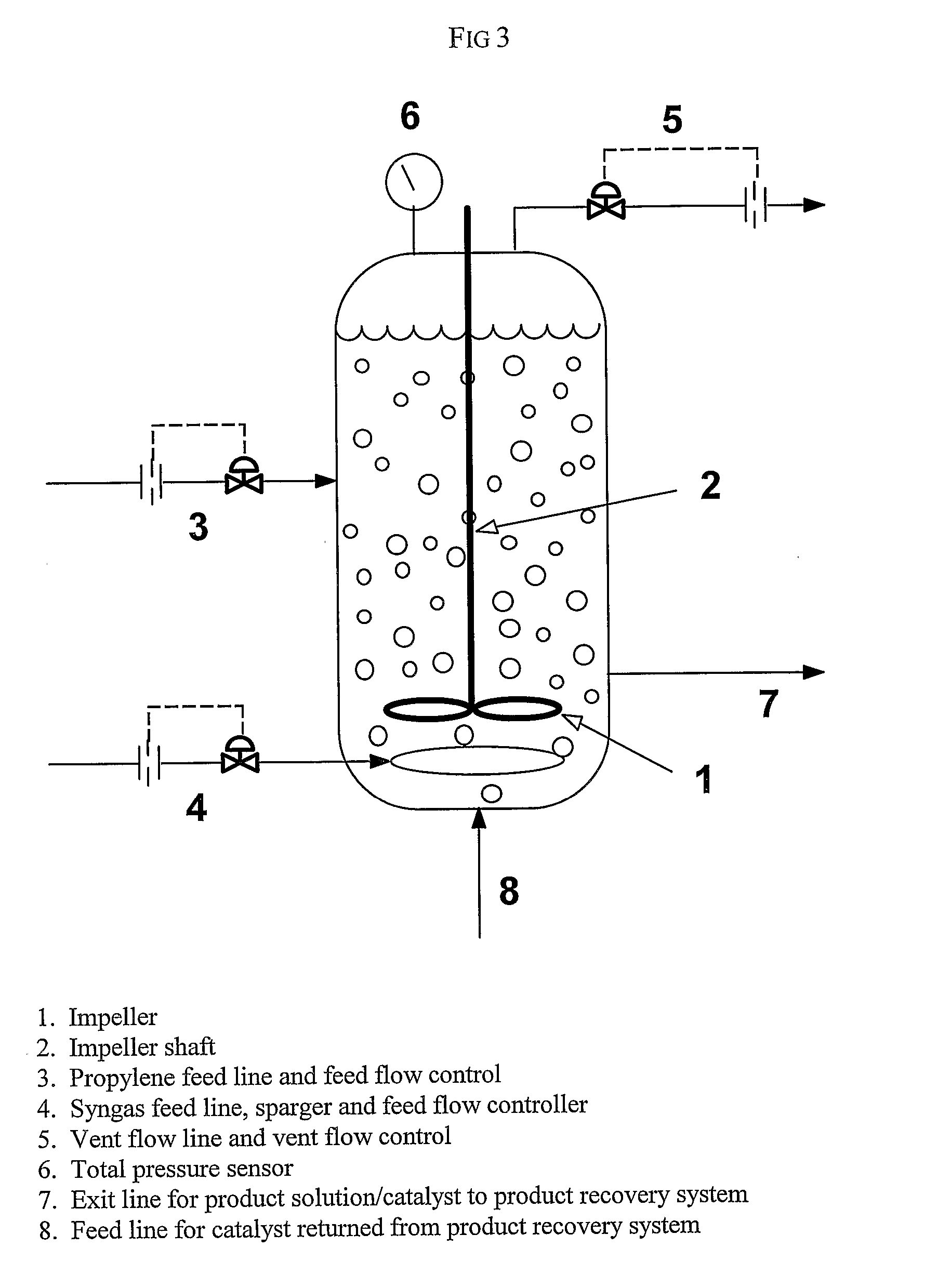
[0168]This example illustrates the method of the invention for determining a primary amount of synthesis gas feed flow rate for operation in the inverse carbon monoxide partial pressure region of operation. A reactor was configured as shown in FIG. 3. The reactor was equipped with an impeller (1), impeller shaft (2), propylene feed line and feed flow control (3); syngas feed line and feed flow control (4), the feed line terminating in a sparger in the reactor; vent flow line and vent flow control (5), total pressure sensor (6), exit line for product solution / catalyst to product recovery system (7), and feed line for catalyst returned from product recovery system (8). During the experiment the propylene feed flow rate and reactor vent flow rate were maintained constant within practical limits. To maintain a constant catalyst liquid level and achieve steady-state operation, a portion of the reaction solution was continuously removed from the reactor and passed through a product recove...

example 2

[0173]Example 2 illustrates stable operation of a hydroformylation process in the negative order region of the hydroformylation rate curve in accordance with the invention. The reactor was configured as shown in FIG. 4, which was identical to the reactor configuration of FIG. 3 with the exception that the syngas feed flow control comprised primary (4) and secondary (9) flow control valves. Operating parameters were controlled in a manner similar to Example 1. A primary amount of synthesis gas was fed to the reactor through the primary synthesis gas flow rate controller (4). In response to deviations of the measured total pressure from the target pressure of 120 psig (827 kPa), an additional amount of synthesis gas was fed through the secondary forward pressure regulator (9) to adjust the total reactor pressure to the target pressure. The reaction conditions were maintained until steady-state conditions were achieved as indicated by a constant total reactor pressure and constant hydr...

example 3

[0178]This example illustrates how to bring stable operation to the reaction system of Comparative Experiment 1. From the final conditions described in Comparative Experiment 1, the total synthesis gas feed rate was decreased to 180 SLH, and the time clock was set back to 0, Subsequently, at 0.20 hours of operation the total reactor vent flow rate had decreased below 17 SLH, and at that point the reactor was rapidly reconfigured (9). Without any further changes, the reaction system quickly reestablished the desired stable operating conditions similar to those in Example 2. The following operating conditions were maintained: propylene feed rate, 299 grams / hour; internal catalyst temperature, 75° C.; syngas feed ratio (H2:CO), 1.06 with a primary feed flow rate of 202 SLH; total reactor pressure, 120 psig (using the synthesis gas feed pressure regulator); and reactor vent flow rate, 44 SLH. The reactor vent flow rate of 44 SLH was sufficient to purge inert components and by-products f...


PUM

PropertyMeasurementUnit
carbon monoxide partial pressureaaaaaaaaaa
temperatureaaaaaaaaaa

Abstract

An improved hydroformylation process involving reacting one or more reactants, such as an olefin, with carbon monoxide and hydrogen in the presence of a hydroformylation catalyst, to produce a reaction product fluid comprising one or more products, preferably aldehydes; wherein said process is conducted in a region of the hydroformylation rate curve that is negative or inverse order in carbon monoxide, which is sufficient to prevent and / or lessen deactivation of the hydroformylation catalyst; and wherein total pressure is controlled at a predetermined target value and / or vent flow rate is controlled at a predetermined target value, by adjusting a flow of a carbon-monoxide containing inlet gas, so as to prevent and / or lessen cycling of process parameters, e.g., reaction rate, total pressure, vent flow rate, and / or temperature.

Description

[0001]This application is a 371 filing of International Patent Application No. PCT / US2005 / 025571, filed Jul. 19, 2005, which claims the benefit of U.S. Provisional Patent Application Ser. No. 60 / 598,032, filed Aug.2, 2004.BACKGROUND OF THE INVENTION[0002]This invention pertains to a method of stabilizing a hydroformylation process against rapid, often extreme, change or cycling of reaction rate and / or process parameters, such as total pressure, vent flow rate, and temperature.[0003]It is well known in the art that aldehydes may be readily produced by reacting an olefinically unsaturated compound with carbon monoxide and hydrogen in the presence of a metal-organophosphorus ligand complex catalyst, and that preferred processes involve continuous hydroformylation and recycling of a solution containing a Group VIII-organopolyphosphite ligand complex catalyst. Rhodium is a preferred Group VIII metal. Such art is exemplified in U.S. Pat. No. 4,148,830; U.S. Pat. No. 4,717,775; and U.S. Pa...

Claims


Application Information

Patent Timeline
Patent Type & Authority Patents(United States)
IPC IPC(8): C07C45/50
CPCC07C45/50C07C47/02C07C45/49
Inventor PETERSON, RONALD REISENSCHMID, THOMAS C.BRYANT, DAVID R.MOKHTARZADEH, MORTEZA
Owner DOW TECH INVESTMENTS
Why Eureka
Try Eureka